A virtual eyepiece device for eye movement monitoring

A technology of eyepieces and human eyes, which is applied in the direction of eye test equipment, applications, magnifying glasses, etc., can solve the problems of high test environment requirements, many interference factors, and high proportion of subjective factors in test results, and achieve convenience and comfort. required effect

Inactive Publication Date: 2017-12-08
ISEN TECH & TRADING
View PDF5 Cites 0 Cited by
  • Summary
  • Abstract
  • Description
  • Claims
  • Application Information

AI Technical Summary

Problems solved by technology

However, the latter requires the assistance of a doctor, and has high requirements for the test environment, many interference factors, and a high proportion of subjective factors in the test results.

Method used


Image

  • A virtual eyepiece device for eye movement monitoring
  • A virtual eyepiece device for eye movement monitoring

Examples


Embodiment 1

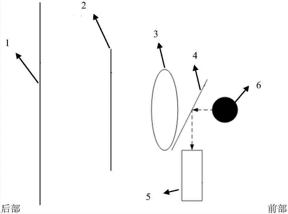
[0023] figure 1 It is a schematic structural diagram of a virtual imaging eyepiece device according to an embodiment of the present invention, such as figure 1 As shown, the inside of the eyepiece device is provided with a lens assembly 3, a human eye test area, a microdisplay 2, a camera assembly 5 and a data transmission assembly, wherein the lens assembly is composed of two lens groups arranged on the left and right, and the microdisplay is located in the lens assembly. At the rear of the lens assembly, there are two human eye test areas on the left and right correspondingly. The camera assembly includes two camera assemblies, and the two camera assemblies are respectively facing the two human eye test areas. Components are connected to the controller for data transfer.

[0024] The lens group consists of two aspheric mirrors, one of which is a convex mirror with a diameter range of 20-40mm and a central thickness of 10-18mm; the other is a concave mirror with a diameter o...

Embodiment 2

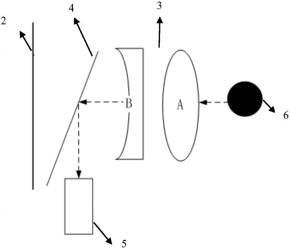
[0028] figure 2 It is a structural schematic diagram of a virtual imaging eyepiece device according to another embodiment of the present invention. The difference between it and Embodiment 1 is that the two camera assemblies of the camera assembly are respectively located at the rear of the two lens groups correspondingly; There is a reflective lens with an angle of 36° with the horizontal direction, which is used for the camera component to record the image of the eyeball. The center axis distance between the camera component and the lens group is 23-27mm, and the horizontal distance between the camera component and the lens group is 16mm-20mm. Such a design provides a large viewing angle and a reduced thickness, improving wearing comfort. However, there is a problem that a specific optical design is required to correct image distortion, and the optical design is complicated.


PUM


Abstract

The invention relates to a virtual eyepiece device for monitoring eyeball movement. The virtual eyepiece device comprises an eyepiece frame which is internally provided with a lens assembly, two human eye testing areas, a micro display, a camera assembly and a data transmission assembly; the lens assembly is composed of two lens sets which are arranged in a left and right mode; the micro display is located at the back of the lens assembly, and the human eye testing areas are correspondingly arranged in front of the lens assembly in a left and right mode; the camera assembly comprises two camera components which face the two human eye testing areas respectively; the data transmission assembly connects the micro display and the camera assembly with a computer respectively. According to the virtual eyepiece device, by mean of combination of a virtual imaging eyepiece and computer software, interference of the outside world to the testing process is reduced, dynamic visual acuity testing is standardized, reliable eyeball movement feature data can be obtained, and a scientific basis is provided for subsequent dynamic visual acuity feature evaluation.

Description

technical field [0001] The invention relates to a virtual eyepiece device, in particular to a virtual eyepiece device for eye movement monitoring. Background technique [0002] At present, the common vision detection method is to use a static eye chart, while the ordinary dynamic vision test mainly detects the relative motion characteristics between the subject and the visual target. However, the latter requires the assistance of a doctor, and has high requirements for the test environment, many interference factors, and a high proportion of subjective factors in the test results. [0003] The present invention-the dynamic vision inspection equipment can effectively eliminate environmental interference, and can display various simple or complex vision inspection signals according to needs, especially can use virtual imaging technology in the eyepiece to check other indicators such as depth of field and stereo vision. At the same time, it can collect eye images during visual...

Claims


Application Information

Patent Timeline
Patent Type & Authority Patents(China)
IPC IPC(8): A61B3/113G02B27/01G02B25/00
CPCA61B3/113G02B25/001G02B27/017
Inventor 刘志勇刘甘林
Owner ISEN TECH & TRADING
Why Eureka
Try Eureka