Eyeball motion monitoring system based on virtual reality

A technology of eye movement and monitoring system, which is applied in the fields of eye testing equipment, medical science, optometry, etc. It can solve the problems of high proportion of subjective factors in test results, high test environment requirements, and many interference factors, so as to achieve clear detection methods , accurate and reliable data, simple algorithm effect

Inactive Publication Date: 2016-12-14
ISEN TECH & TRADING
View PDF11 Cites 23 Cited by
  • Summary
  • Abstract
  • Description
  • Claims
  • Application Information

AI Technical Summary

Problems solved by technology

However, the latter requires the assistance of a doctor, and has high requirements for the test environment, many interference factors, and a high proportion of subjective factors in the test results.

Method used


Image

  • Eyeball motion monitoring system based on virtual reality
  • Eyeball motion monitoring system based on virtual reality
  • Eyeball motion monitoring system based on virtual reality

Examples


Embodiment 1

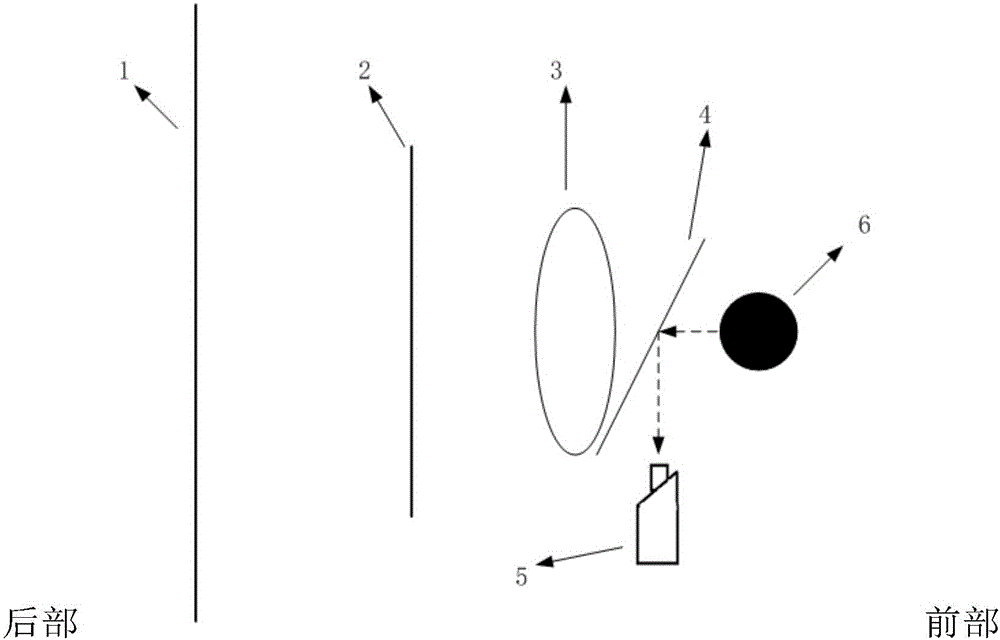
[0061] figure 1 It is a schematic structural diagram of a virtual imaging eyepiece device according to an embodiment of the present invention, such as figure 1 As shown, the inside of the eyepiece device is provided with a lens assembly 3, a human eye test area, a microdisplay 2, a camera assembly 5 and a data transmission assembly, wherein the lens assembly is composed of two lens groups arranged on the left and right, and the microdisplay is located in the lens assembly. At the rear of the lens assembly, there are two left and right human eye test areas correspondingly in front of the lens assembly. The camera assembly includes two cameras, and the two cameras are respectively facing the two human eye test areas. The data transmission assembly connects the microdisplay and the camera assembly with the control Connector connection for data transmission.

[0062] The lens group consists of two aspheric mirrors, one of which is a convex mirror with a diameter range of 20-40mm ...

Embodiment 2

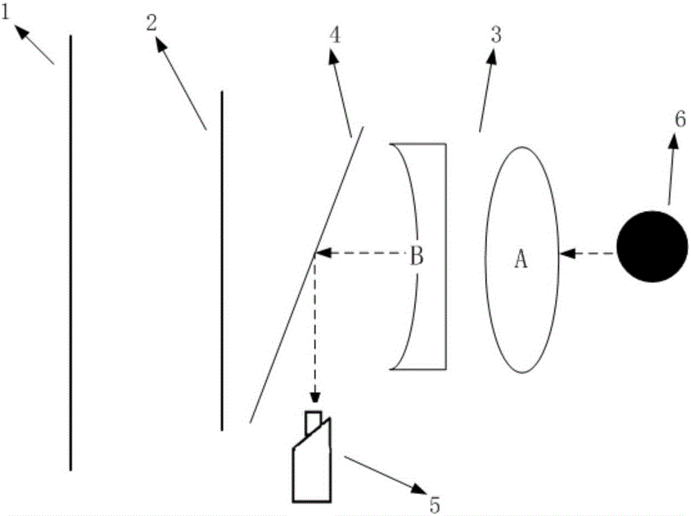
[0066] figure 2 It is a structural schematic diagram of a virtual imaging eyepiece device according to another embodiment of the present invention, and its difference from Embodiment 1 is that the two cameras of the camera assembly are respectively located at the rear of the two lens groups correspondingly; The reflective lens with an included angle of 36° is used for the camera component to record the image of the eyeball. The center axis distance between the camera and the lens group is 23-27mm, and the horizontal distance between the camera and the lens group is 16mm-20mm. Such a design provides a large viewing angle and a reduced thickness, improving wearing comfort. However, there is a problem that a specific optical design is required to correct image distortion, and the optical design is complicated.

Embodiment 3

[0068] The micro-display forms a virtual image plane after being magnified by the lens group, then assuming that there is a target B displayed on the display position as Bl, Br, then the display position of the target B on the virtual image plane becomes L1, R1, and the distance between them is Parallax P, the distance between the virtual image plane and the eyes is L, and the interpupillary distance is D, then the final fused target observed by both eyes is viewpoint A, and the stereoscopic perception depth of viewpoint A is V, then the relationship between these variables is as follows: The above formula says:

[0069] V=L*P / (P-D)

[0070] According to the above formula, assuming that the distance between the virtual image plane of the virtual reality display module and the eyes is specified as 1000mm, and the resolution of the micro-display is W*H, the three-dimensional object required to be formed should be located on the virtual image screen, that is, V=0, then the object...


PUM


Abstract

An eyeball motion monitoring system based on virtual reality comprises a virtual image display module and an eyeball motion track image collection module, wherein the virtual image display module comprises a virtual imaging eye lens device and an imaging positioning module; and the eyeball motion track image collection module comprises a pupil positioning and processing module, an eyeball deflection angle mapping and computation module and a data collection module. The system provided by the invention has the advantages that through combined utilization of a virtual imaging eye lens and computer software, external interference to detection courses can be reduced; dynamic vision detection is standardized; reliable eyeball motion characteristic data can be obtained; and a scientific basis can be provided for subsequent dynamic vision characteristic evaluation.

Description

technical field [0001] The invention relates to an eye movement monitoring system, in particular to a virtual reality eye movement monitoring system based on a virtual imaging eyepiece. Background technique [0002] At present, the common vision detection method is to use a static eye chart, while the ordinary dynamic vision test mainly detects the relative motion characteristics between the subject and the visual target. However, the latter requires the assistance of a doctor, and has high requirements for the test environment, many interference factors, and a high proportion of subjective factors in the test results. [0003] Dynamic vision inspection equipment should be able to effectively eliminate environmental interference, display various simple or complex vision inspection signals according to needs, especially use virtual imaging technology in the eyepiece to check depth of field, stereo vision and other indicators. At the same time, it can collect eye images durin...

Claims


Application Information

Patent Timeline
Patent Type & Authority Applications(China)
IPC IPC(8): A61B3/113A61B3/103G02B27/01G02B25/00
CPCA61B3/103A61B3/113G02B25/001G02B27/017
Inventor 刘志勇刘甘林
Owner ISEN TECH & TRADING
Why Eureka
Try Eureka