
Electric intra-cavity incision anastomat with emergent tool retracting device

A stapler and internal cutting technology, applied in the direction of surgical fixation nails, etc., can solve the problems that the stapler cannot be taken out, the motor cannot be rotated, etc., and achieve the effect of simple structure, reliable safety performance, and easy operation

Active Publication Date: 2016-06-08
SHANDONG WEIRUI SURGICAL MEDICAL PROD
View PDF5 Cites 18 Cited by
  • Summary
  • Abstract
  • Description
  • Claims
  • Application Information

AI Technical Summary

Problems solved by technology

[0004] The present invention aims at the technical problems that the existing electric intracavity cutting stapler may not be able to rotate after the motor is accidentally turned off, which brings surgical risks and the stapler cannot be taken out, and provides a safe and reliable belt that can still take out the stapler after power failure. Electric Endovascular Cutting Stapler with Emergency Knife Retraction Device

Method used


Image

  • Electric intra-cavity incision anastomat with emergent tool retracting device
  • Electric intra-cavity incision anastomat with emergent tool retracting device
  • Electric intra-cavity incision anastomat with emergent tool retracting device

Examples


Embodiment 1

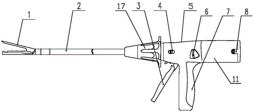
[0032] Such as figure 1 As shown, the present invention is provided with a stapler body 11, and the stapler body 11 is provided with a jaw 1, a sleeve 2, a rotary switch 17, a closing handle 3, a knife reversing switch 4, an unlocking switch 6, a fixed handle 7 and a battery pack 8.

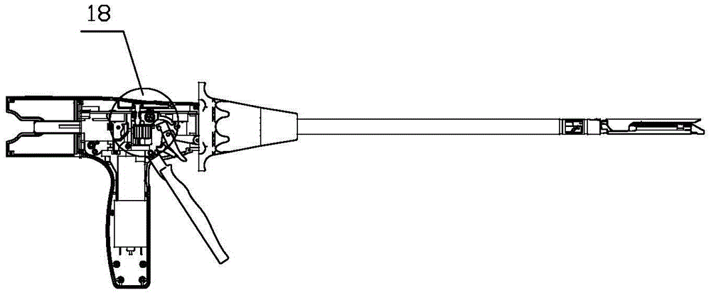
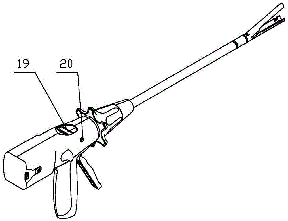
[0033] The upper part of the stapler body 11 is provided with a manual retraction knob groove, and a manual retraction knob 5 is provided in the manual retraction knob groove, and the manual retraction knob 5 can be taken out from the manual retraction knob groove when needed . Such as figure 2 The position shown is the emergency knife retracting device 18 of the present invention, and the manual knife retracting knob 5 is also a part of the emergency knife retracting device 18 . Such as image 3 As shown, the present invention is provided with a first emergency retraction hole 19 at the top of the stapler, and a second emergency retraction hole 20 is provided at the side of the stapler.

...

Embodiment 2

[0045] Embodiment 2 is basically the same as Embodiment 1, and the similarities will not be repeated, and the differences will be described below.

[0046] The stapler body 11 is provided with a fixed handle 7, as shown in 9 and Figure 10 As shown, a handle loamer 28 is provided above the fixed handle 7, and the handle loamer 28 is also provided with an extending end 24. The effect of the handle upper cover 28 is the same as that of the manual knife retraction knob 5 in Embodiment 1, all of which utilize their protruding end 24 to push down the transmission gear pressing block 10 when the emergency knife retraction device is enabled. Such an arrangement makes the manual knife retraction knob 5 a part of the stapler body 11 , which has a simpler structure and stronger integrity.

[0047] Such as Figure 11 As shown, the transmission gear pressing block 10 is provided with a limiting groove 29, and the stapler body 11 is provided with a limiting piece 30, and the limiting pie...


PUM


Abstract

The invention provides an electric intra-cavity incision anastomat with an emergent tool retracting device. The anastomat solves the technical problems that an existing electric intra-cavity incision anastomat can not operate due to accidental shutdown of a motor, and as a result, the anastomat can not be taken out. The anastomat is provided with an anastomat body. The anastomat body is provided with a jaw, a sleeve, a closing handle, a fixed handle, an end gear, a transmission gear and a rack. The transmission gear can be meshed with the end gear and the rack. A hinge pin is arranged in the transmission gear. A spring is arranged on the hinge pin. The emergent tool retracting device is provided with a manual tool retracting instrument, a transmission gear pressing block and a tool retracting gear. The tool retracting gear is meshed with the rack. The anastomat is widely applied to the medical field.

Description

technical field [0001] The invention relates to an electric endo-cavity cutting stapler, in particular to an electric endo-cavity cutting anastomat with an emergency knife retracting device. Background technique [0002] At present, the electric endovascular cutting stapler has been widely used in various open or minimally invasive general surgery, obstetrics and gynecology, urology, thoracic surgery and pediatric operations. [0003] During the operation, the electric motor can provide the power source for the cutter and stapler, which saves time and effort in the operation. However, once the electric motor fails to rotate due to problems such as accidental flameout, the instrument must be taken out immediately and replaced with a new one. At this time, it is very difficult Maybe the instrument is still locked, the cutting knife is in the cutting anastomosis line, unable to move, the jaws cannot be opened, the clamped tissue cannot be separated from the jaws, and the staple...

Claims


Application Information

Patent Timeline
Patent Type & Authority Applications(China)
IPC IPC(8): A61B17/072
CPCA61B17/07207A61B2017/07214
Inventor 姚大强刘启东陈兆伟冷和恩夏玉波王小芳
Owner SHANDONG WEIRUI SURGICAL MEDICAL PROD
Learn More