Automatic flow control method for perfusion suction system

A suction tube and suction device technology, applied in the field of medical devices, can solve the problems of increased surgical complexity, insufficient safety and stability, difficult surgery, etc., so as to reduce the time consumed by manual operations, simplify the complexity of surgery, and speed up the surgical process. Effect

Inactive Publication Date: 2020-01-03
陈艺成
View PDF6 Cites 2 Cited by
  • Summary
  • Abstract
  • Description
  • Claims
  • Application Information

AI Technical Summary

Problems solved by technology

[0003] At present, the perfusion suction system is generally equipped with only one pressure sensor to measure the patient's inner cavity, but the simple pressure sensor is not very accurate in measuring the cavity pressure, the value fluctuates greatly, and the safety and stability are not enough; secondly, the pressure sensor senses the pressure in the cavity. , the perfusion part will stop, and the water in the cavity will no longer flow, making the surgical field of view not clear enough, making the operation difficult, and the patient also has potential safety hazards. Automatic adjustments lead to unstable pressure and volume in the cavity, and doctors need to adjust them by themselves, which increases the complexity of the operation

Method used


Image

  • Automatic flow control method for perfusion suction system
  • Automatic flow control method for perfusion suction system
  • Automatic flow control method for perfusion suction system

Examples


Embodiment Construction

[0032] In order to facilitate those skilled in the art to better understand the present invention, the present invention will be described in further detail below in conjunction with the accompanying drawings and specific embodiments. The following is only exemplary and does not limit the protection scope of the present invention.

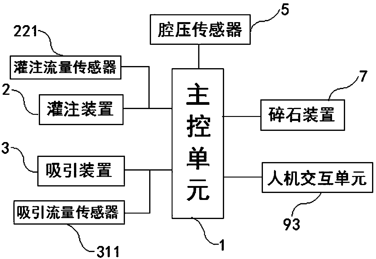
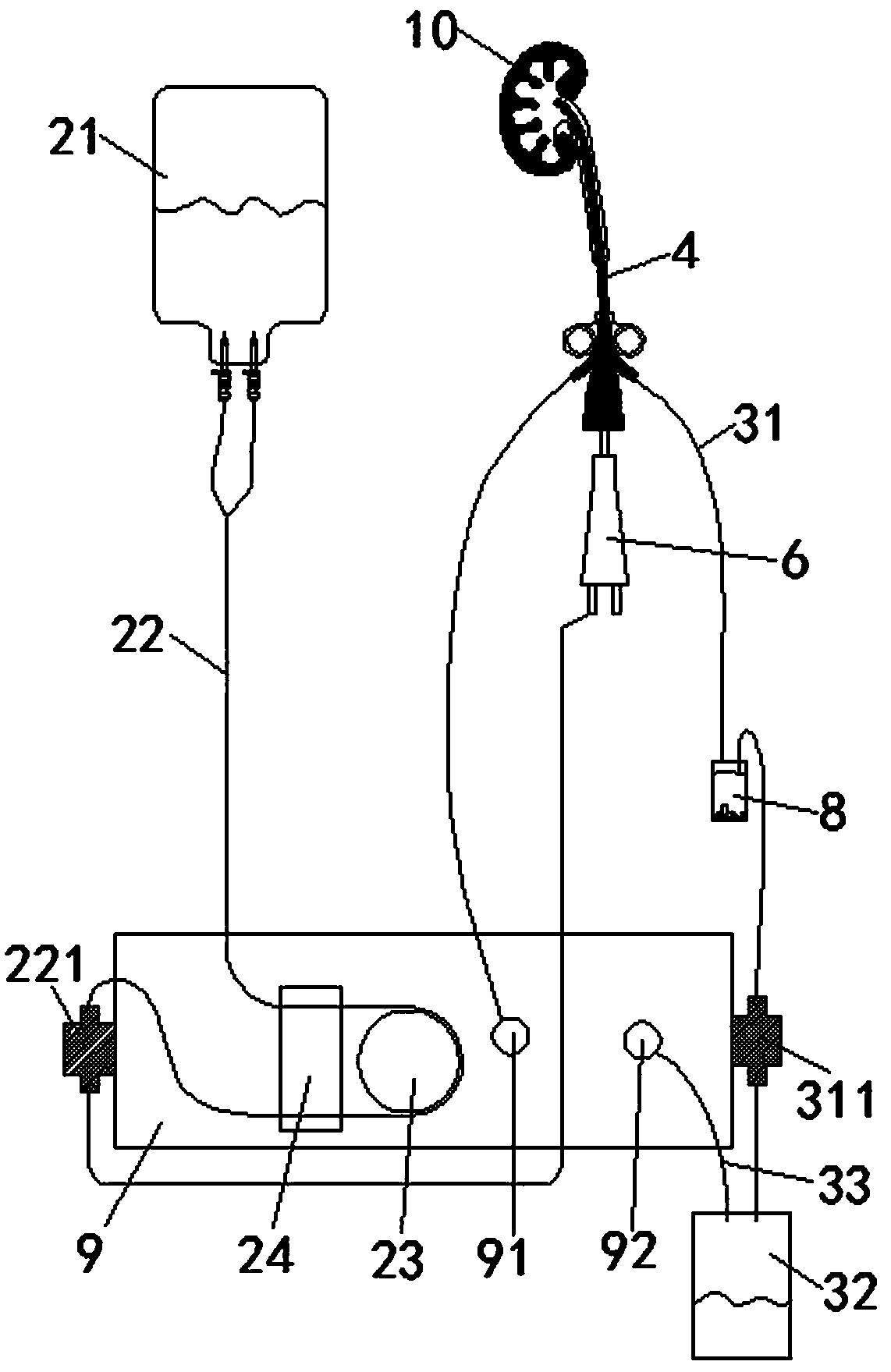
[0033] Such as figure 1 and 2 As shown, an automatic flow control method for a perfusion suction system described in this embodiment, the perfusion suction system includes a main control unit 1, a perfusion device 2, a suction device 3, a mirror sheath 4, and a The chamber pressure sensor 5, the perfusion device 2, the suction device 3 and the chamber pressure sensor 5 are all connected to the main control unit 1.

[0034] In this embodiment, the perfusion device 2 includes a liquid storage device 21, a hose 22 connecting the liquid storage device and the mirror sheath, and a driving device for driving the liquid in the hose. Further, the driving ...


PUM


Abstract

The invention discloses an automatic flow control method of a perfusion suction system. The perfusion suction system comprises a main control unit, a perfusion device, a suction device, an endoscope sheath and a cavity pressure sensor, wherein a perfusion flow sensor is arranged on a hose of the perfusion device, and a suction flow sensor is provided on a suction tube of the suction device. The automatic flow control method comprises the following steps: S1, presetting at least intracavity pressure, intracavity volume, perfusion flow, suction flow and suction pressure, and then starting to work; S2, at the beginning, the perfusion device starts to work, liquid enters a cavity of a patient through the endoscope sheath, at this time, the suction device does not work, and when one of the intracavity pressure and the intracavity volume reaches the set value, the suction device starts to work; and S3, when one of the intracavity pressure and the intracavity volume reaches the set value, thesuction flow and the perfusion flow automatically enter a synchronous state, namely the suction flow and the perfusion flow are equal. The perfusion flow and the suction flow are in a dynamic adjustment process, the liquid is always flowing, and operation safety is ensured.

Description

technical field [0001] The invention relates to the technical field of medical devices, in particular to an automatic flow control method for a perfusion suction system. Background technique [0002] The perfusion suction system is used in laparoscopic surgery, and usually includes a perfusion device and a suction device. Among them, the perfusion device uses liquid medium to pressurize and expand the patient's inner cavity to form a visible area, and can clean the blood in the cavity, so that the doctor's observation and surgical field of vision are clear; the suction device is used to suck the waste liquid in the patient's inner cavity out of the body. [0003] At present, the perfusion suction system is generally equipped with only one pressure sensor to measure the patient's inner cavity, but the simple pressure sensor is not very accurate in measuring the cavity pressure, the value fluctuates greatly, and the safety and stability are not enough; secondly, the pressure s...

Claims


Application Information

Patent Timeline
Patent Type & Authority Applications(China)
IPC IPC(8): A61M1/00A61B18/26
CPCA61M1/0058A61B18/26A61B2218/002A61B2218/007A61B2018/00863A61B2018/00982A61M1/734A61M1/732A61M1/74
Inventor 陈艺成姚拥军
Owner 陈艺成
Why Eureka
Try Eureka