
Novel deodorizing device

A new and small technology, applied in the direction of gasification substances, etc., can solve the problems of poor heat dissipation effect of the deodorant device, unsatisfactory deodorization effect of the deodorant device, and high overall temperature of the ozone generator, achieving complete functions and simple structure. , easy to use and install

Inactive Publication Date: 2016-06-08
TIANJIN KEYI ELECTRONICS TECH
View PDF5 Cites 1 Cited by
  • Summary
  • Abstract
  • Description
  • Claims
  • Application Information

AI Technical Summary

Problems solved by technology

[0002] At present, people's life rhythm is fast, people's living standards are improving day by day, people's requirements for quality of life are getting higher and higher, and their pursuit of health is becoming more and more urgent. People will also use various methods and equipment to remove odors, but most of the deodorization devices now have unsatisfactory deodorization effects, the deodorization efficiency is not high, and the deodorization device itself does not have a good heat dissipation effect. , the overall temperature of the ozone generator used in some deodorizing devices is high, and the heat dissipation is not good, and the heat dissipation effect is even worse when the power is used
And the function of existing deodorizing device is all comparatively single, mostly only has deodorizing function, thus it can be seen that existing deodorizing device can't fully satisfy the consumer's use, needs to develop a kind of new deodorizing device urgently

Method used


Image

  • Novel deodorizing device
  • Novel deodorizing device
  • Novel deodorizing device

Examples


Embodiment Construction

[0024] In order to further understand the content, characteristics and effects of the present invention, the following examples are given, and detailed descriptions are given below with reference to the accompanying drawings. It should be noted that this embodiment is descriptive, not restrictive, and cannot thereby limit the protection scope of the present invention.

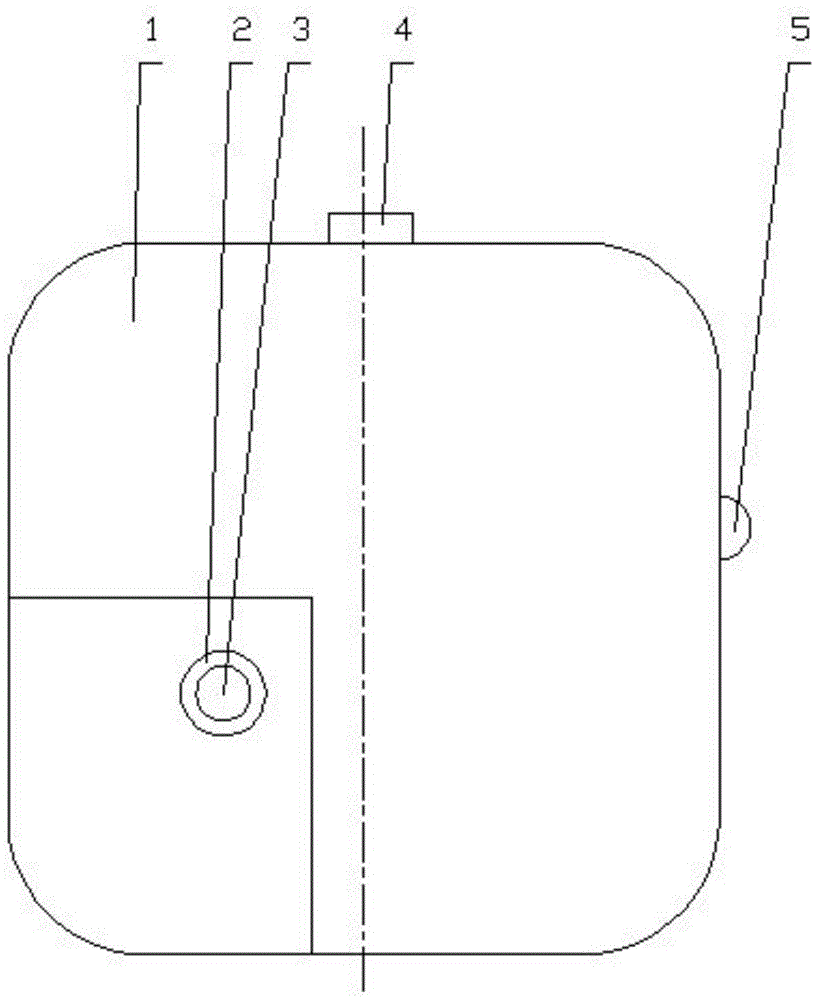
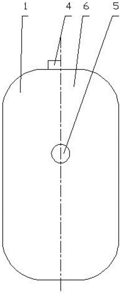
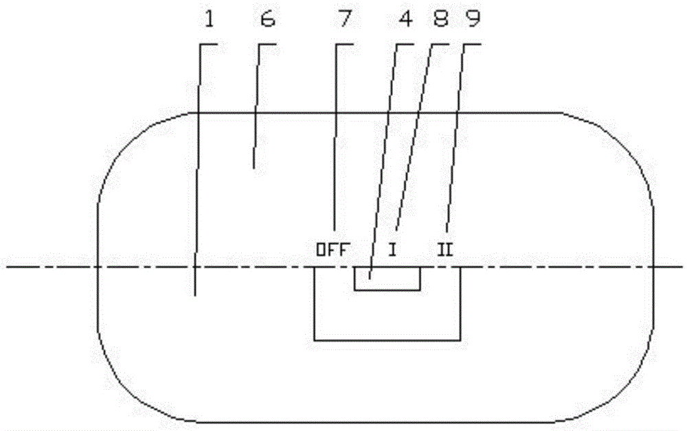
[0025] A new type of deodorization device, such as figure 1 , figure 2 , image 3 , Figure 4 with Figure 5 As shown, the device includes a front housing 1, a rear housing 6, a control circuit board (PCB board) 17, an ozone generator, an ozone hole 2, a photosensitive sensor display light 5, a switch 4, a small fan 12 and a plug 10 , the front shell and the rear shell are installed together, and the rear shell is evenly spaced along the circumferential direction with four screw-mounted columns 13, and the screw-mounted columns are connected to the control circuit board through a screw 14 Together, the oz...


PUM

PropertyMeasurementUnit
thicknessaaaaaaaaaa

Abstract

The invention relates to a novel deodorizing device. According to the novel deodorizing device, four threaded mounting studs are uniformly distributed on a rear shell at intervals along the peripheral direction, a screw is mounted in each threaded mounting stud, so that the rear shell is connected to a control circuit board in a meshing manner, an ozone dissipation hole is formed in a front shell, a small fan and air vent holes are also arranged, ozone produced by an ozone generator escapes from the ozone dissipation hole, and the threaded mounting studs adopt the multi-section compound drawing angles. According to the novel deodorizing device, the ozone generator is arranged, directly contacts the air, and is of open type, so that the ozone production efficiency is high, the heat dissipation is extremely good, the produced ozone has extremely good diffusibility and good deodorizing effect, and the deodorizing efficiency is improved; in addition, the threaded mounting studs adopt the multi-section compound drawing angles, the structure enables a mold to be smoothly drawn out after a workpiece is formed, the side wall surface of the workpiece is prevented from being damaged, the areas of round holes in the tops of the threaded mounting studs can not be too large, so that the artistic appearance can not be influenced, the stability of the workpiece is also prevented from being influenced, and the threaded mounting studs are simple in structure, and convenient to manufacture, use and mount.

Description

technical field [0001] The invention belongs to the technical field of deodorization equipment, in particular to a novel deodorization device. Background technique [0002] At present, people's life rhythm is fast, people's living standards are improving day by day, people's requirements for quality of life are getting higher and higher, and their pursuit of health is becoming more and more urgent. People will also use various methods and equipment to remove odors, but most of the deodorization devices now have unsatisfactory deodorization effects, the deodorization efficiency is not high, and the deodorization device itself does not have a good heat dissipation effect. , The overall temperature of the ozone generator used in some deodorization devices is high, and the heat dissipation is not good, and the heat dissipation effect is even worse when the power is used. And the function of existing deodorizing device is all comparatively single, mostly only has deodorizing fun...

Claims


Application Information

Patent Timeline
Patent Type & Authority Applications(China)
IPC IPC(8): A61L9/12A61L101/10
Inventor 赵广艺安昕昇安军孙鹏磊
Owner TIANJIN KEYI ELECTRONICS TECH
Learn More