A dust collector filter element cleaning measurement and control device

A technology of measurement and control devices and dust collectors, which is applied in the direction of instruments, simulators, program control, etc., can solve problems such as energy waste, equipment wear, and failure to achieve dust cleaning effect, so as to reduce wear, improve service life, and run cycle long effect

Active Publication Date: 2017-07-25
HENAN DRAGON INTO COAL TECH CO LTD
View PDF8 Cites 0 Cited by
  • Summary
  • Abstract
  • Description
  • Claims
  • Application Information

AI Technical Summary

Problems solved by technology

If the blowback time is too early or too long, it will cause waste of energy and increased wear of equipment. If the blowback time is too late or too short, it is not conducive to timely and effective cleaning of dust, and the cleaning effect cannot be achieved. Therefore, it is urgent Need to make further improvement and innovation in dust removal measurement and control of dust collector filter element

Method used


Image

  • A dust collector filter element cleaning measurement and control device
  • A dust collector filter element cleaning measurement and control device
  • A dust collector filter element cleaning measurement and control device

Examples


Embodiment 1

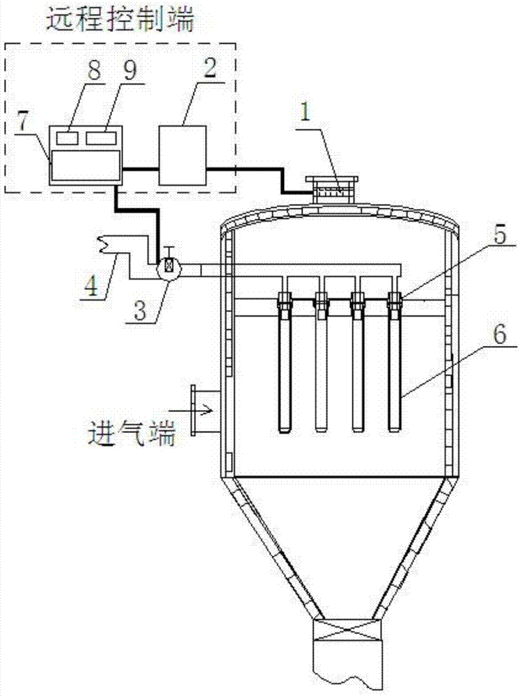
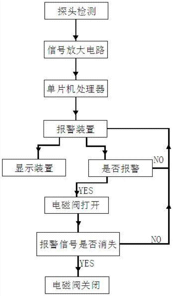
[0027] Such as figure 1 , figure 2 , image 3 As shown, a dust removal measurement and control device for a filter element of a dust collector includes a detection sensor, an alarm device and a control device. The detection sensor includes a probe 1 and a signal processor 2 connected to the probe, and the probe is located at the air outlet of the output end of the filter element. The input end of the alarm device is connected to the output end of the signal processor, and the output end of the alarm device is connected to the input end of the control device.

[0028] The signal processor includes a signal amplifying circuit and a single-chip processor connected in sequence.

[0029] Described control device is electromagnetic control valve 3, and described electromagnetic control valve is connected blowing gas conveying pipe 4, and is provided with nozzle 5, and described nozzle contacts with filter core 6 of dust remover and corresponds one by one, and described blowing ga...

Embodiment 2

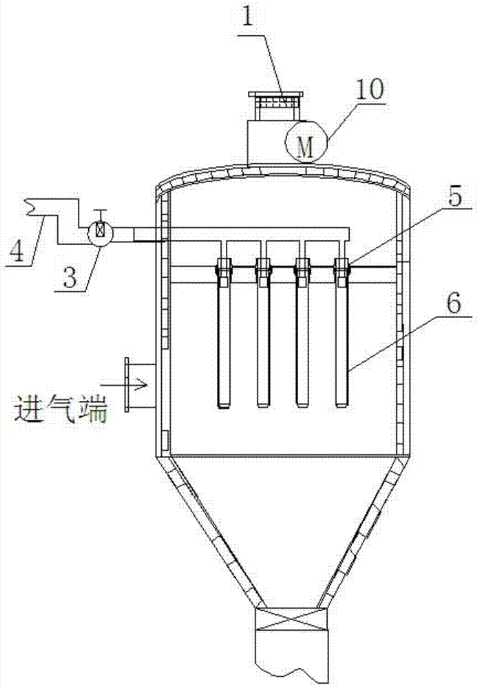
[0045] A dust removal measurement and control device and measurement and control method for a filter element of a dust collector. The difference from Embodiment 1 is that in the equipment involved, a centrifugal fan 10 is installed at the air outlet of the dust collector, and the detection sensor probe 1 is installed at the air outlet of the centrifugal fan. .

Embodiment 3

[0047] A dust removal measurement and control device and a measurement and control method for a filter element of a dust collector, the difference from Embodiment 1 is that the measured gas of the detection sensor is hydrogen sulfide H in dusty gas 2 S, the difference in principle is that the redox reaction of the measured gas on the sensitive electrode is different, and the equation is:

[0048] Hydrogen sulfide (H 2 S): H 2 S+4H 2 O→H 2 SO 4 +8H + +8e - .


PUM


Abstract

The invention discloses an ash removal measuring and control device of a filter element of a dust remover. The device comprises a detecting sensor, a warning device and a control device; the detecting sensor includes a probe and a signal processor connected with the probe; the probe is positioned in a gas outlet in an output end of the filter element; the control device is an electromagnetic control valve; and the electromagnetic control valve is connected with an injected gas conveying pipe, and is provided with nozzles. The device is reasonable in design, safe and reliable, long in operation period, high in regeneration performance of the filter element and accurate and quick in judgment of the ash accumulating condition of the filter element of the dust remover, and can work under high-temperature and high-pressure conditions; after automatic injecting detection is realized, the filter efficiency of the dust remover is increased byabove 10%; an injecting device is intelligently used to largely reduce the wear and to effectively reduce the equipment cost; and the device is excellent in popularization and application value.

Description

technical field [0001] The invention belongs to the technical field of blowing dust removal equipment, and in particular relates to a dust removal measurement and control device for a filter element of a dust collector. Background technique [0002] At present, my country's oil and natural gas resources are in short supply, while solar energy, wind energy and other high-tech clean energy are affected by various factors such as region and cost, and cannot be widely promoted. Therefore, coal will remain my country's most important energy source for a long time to come. main primary energy source. [0003] However, there are many problems and challenges in the process of coal conversion and utilization, such as low comprehensive utilization efficiency, serious environmental pollution, shortage of water resources, and large carbon dioxide emissions. inevitable choice. [0004] One of the core processes of efficient and clean coal utilization technology is to deal with the large...

Claims


Application Information

Patent Timeline
Patent Type & Authority Patents(China)
IPC IPC(8): B08B5/02G05B19/042
CPCB08B5/02G05B19/0428G05B2219/2609
Inventor 朱书成赵家亮李金峰庞志峰
Owner HENAN DRAGON INTO COAL TECH CO LTD
Why Eureka
Try Eureka