Punching device for positioned processing and opening cutting and trimming of micromotor support plate

A support plate and micro-motor technology, applied in positioning devices, feeding devices, storage devices, etc., can solve problems such as inability to adjust in real time, many burrs on the edge of the hole, easy deformation of the plate, etc., to achieve accurate positioning and less punching burrs , Improve the effect of processing quality

Inactive Publication Date: 2016-06-08
WUXI SAINENG MICRO MOTOR
View PDF5 Cites 1 Cited by
  • Summary
  • Abstract
  • Description
  • Claims
  • Application Information

AI Technical Summary

Problems solved by technology

The disadvantages of the above-mentioned punching device or punching machine are: punching can only be performed according to the preset punching pressure, which cannot be adjusted in real time, the punching quality is low, the plate is easily deformed, and there are many burrs on the edge of the hole

Method used


Image

  • Punching device for positioned processing and opening cutting and trimming of micromotor support plate
  • Punching device for positioned processing and opening cutting and trimming of micromotor support plate

Examples


Embodiment Construction

[0011] The specific implementation manner of the present invention will be described below in conjunction with the accompanying drawings.

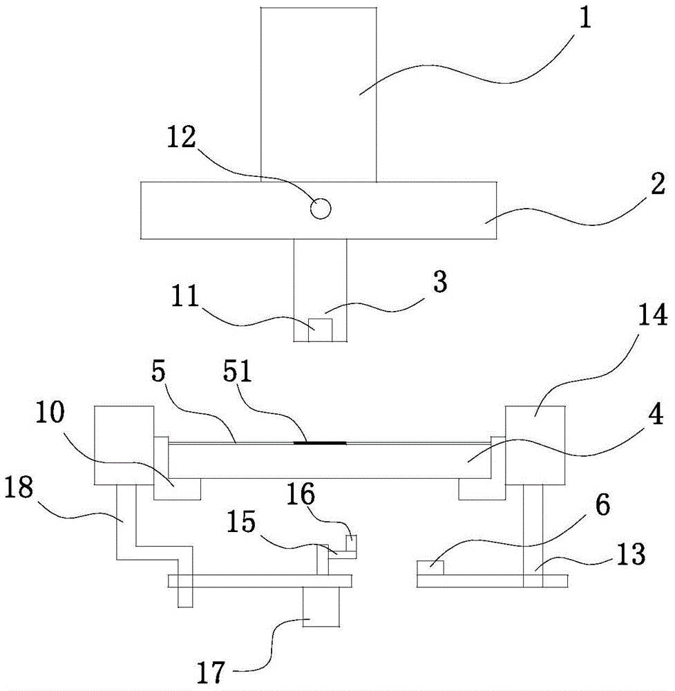
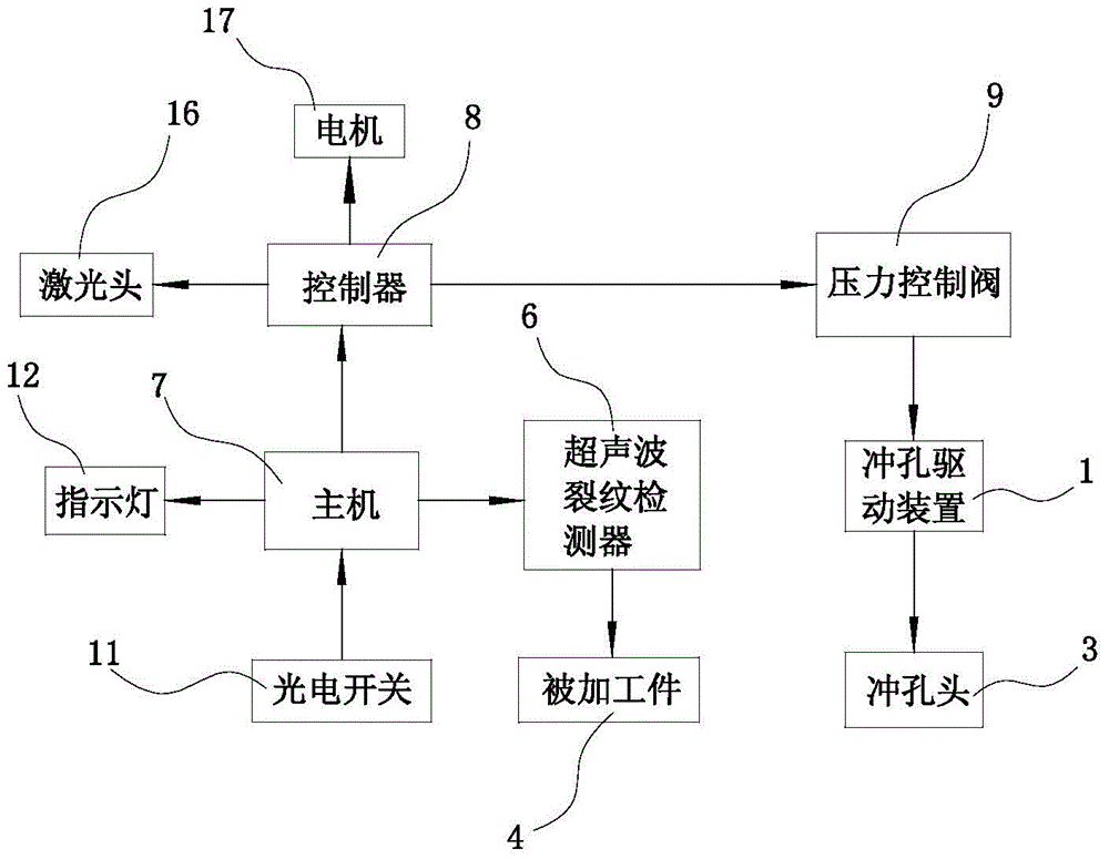
[0012] like figure 1 and figure 2 As shown, the positioning processing of the micro-motor support plate and the punching device for cutting and trimming of the present embodiment include a punching drive device 1, an upper template 2, a punching head 3 and a clamp positioned below the punching head 3. Holding device 10, the micro-motor support plate 4 is installed in the clamping device 10, and also includes a host computer 7, a controller 8, a pressure control valve 9 and an ultrasonic crack detector 6 positioned below the micro-motor support plate 4; punching head 3 A photoelectric switch 11 is built in, and the micro-motor support plate 4 is covered with a film 5 with a color mark 51 for the detection of the photoelectric switch 11; the clamping device 10 is installed on the bracket 14, and the lower surface side of the bracket 14 Th...


PUM


Abstract

The invention relates to a punching device for positioned processing and opening cutting and trimming of a micromotor support plate. The punching device comprises a punching driving device, an upper die plate, a punching head and a clamping device positioned at a position below the punching head, wherein the micromotor support plate is arranged in the clamping device; the punching device also comprises a main unit, a controller, a pressure control valve and an ultrasonic crack detector positioned below the micromotor support plate; an optoelectronic switch is arranged in the punching head; the micromotor support plate is coated with a film; a color mark for detection of the optoelectronic switch is arranged on the film; the clamping device is arranged on a support; the ultrasonic crack detector is arranged at one side of the lower surface of the support by means of a connecting rod; a laser opening cutting device is arranged at the other side of the lower surface of the support by means of a bending frame; and an indicating lamp connected with the main unit is arranged on the front side face of the upper die plate. According to the punching device disclosed by the invention, pinching processing of sheet metal is realized by combining laser opening cutting with punching of the punching head; the punching device is high in processing efficiency and fewer in punching burrs; and the punching device has the characteristics of accuracy in positioning, convenience in operation and small deformation.

Description

technical field [0001] The invention relates to the technical field of motors, in particular to a processing device for a micro-motor support plate. Background technique [0002] The motor is installed in the place of use through the motor frame plate. In order to prevent the motor from shaking or tilting abnormally during use, the mounting holes of the motor frame plate are required to have high precision. Existing punching devices or punching machines all include a frame, a bottom mold fixed on the frame, an upper template that moves up and down relative to the frame, and a punch corresponding to the bottom mold is fixed on the upper template. , the upper template is connected with the oil cylinder or cylinder that drives it to move up and down. Driven by the oil cylinder or air cylinder, the upper template drives the punch to move up and down relative to the bottom mold, so that the required holes are punched out on the micro-motor support plate between the punch and the...

Claims


Application Information

Patent Timeline
Patent Type & Authority Applications(China)
IPC IPC(8): B21D28/26B21D43/00B23K26/361B23K26/70
Inventor 过晓杰
Owner WUXI SAINENG MICRO MOTOR
Why Eureka
Try Eureka