Dip machine

A technology of dipping and slurrying, which is applied in the field of slurrying machines, can solve the problems of high production cost and low utilization rate of slurry, and achieve the effect of increasing utilization rate, reducing usage, and increasing slurry utilization rate

Inactive Publication Date: 2018-01-02
FALCON AEROTECH LTD
View PDF6 Cites 0 Cited by
  • Summary
  • Abstract
  • Description
  • Claims
  • Application Information

AI Technical Summary

Problems solved by technology

[0004] In view of the above problems, the present invention provides a slurry dipping machine, which can solve the problems of low utilization rate of slurry and high production cost of using the traditional rotary bucket scraper type slurry dipping machine to dip the mold shell.

Method used


Image

  • Dip machine
  • Dip machine
  • Dip machine

Examples


Embodiment 1

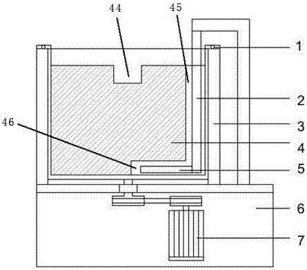
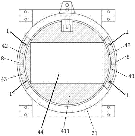
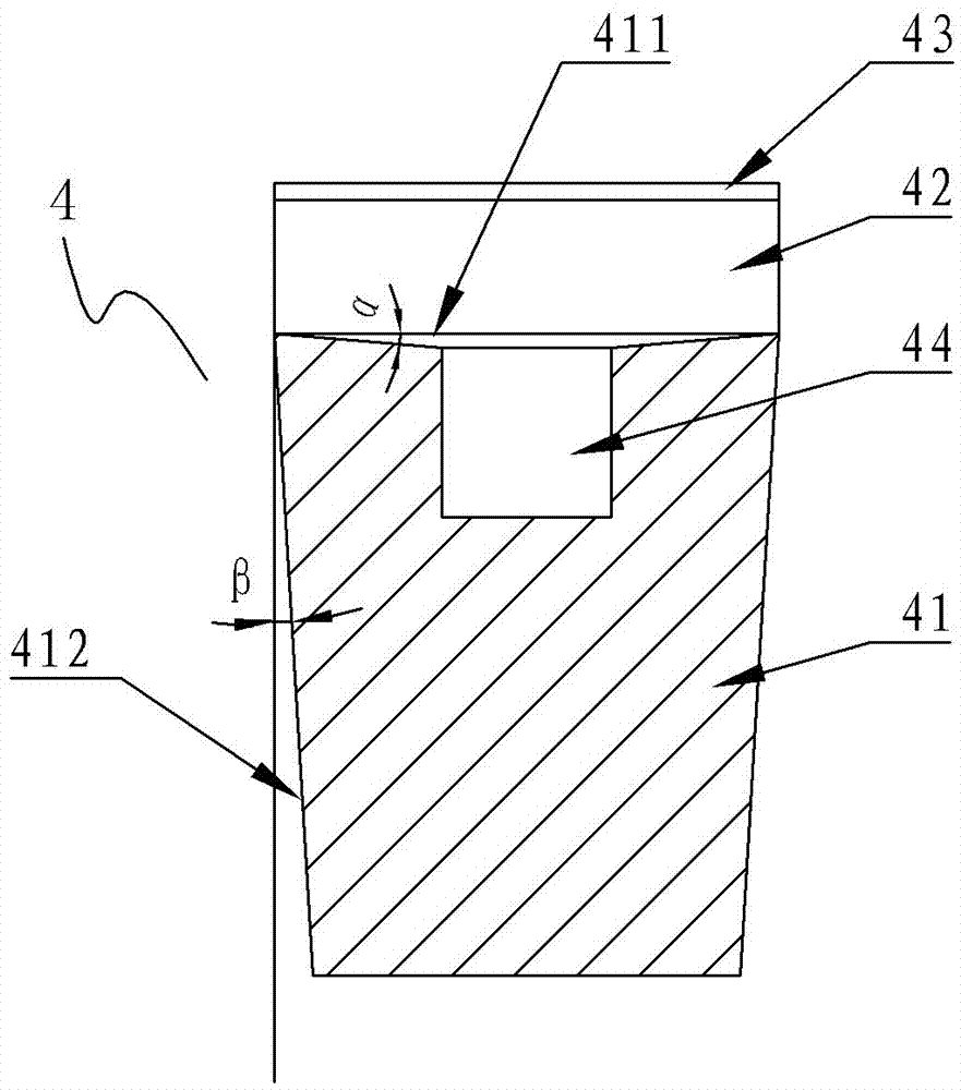
[0021] See figure 1 , the slurry dipping machine of the present invention, which includes a slurry tank 3, a rotary drive device 7, a scraper 5 and an insert 4, the slurry tank 3 is rotatably mounted on a base 6, and a rotary drive device is installed in the base 6 7. The power output end of the rotary drive device 7 is connected to the bottom of the slurry tank 3, the scraper 5 is installed in the slurry tank 2 through the pillar 2, and the insert 4 is detachably filled and installed in the slurry tank 3; the insert 4 It includes a main body 41, a top fastening part 43 and a side connecting part 42. The main body 41 is provided with a cavity 44 for accommodating the mold shell to be dipped. The top fastening part 43 is integrally connected with the main body 41 through the side connecting part 42. The top fastening part 43 is pressed on the barrel wall top surface 31 of the slurry barrel 3 by the positioning pin 1; The fastening part 43 is further pressed against the top sur...

Embodiment 2

[0026] The difference between the second embodiment and the first embodiment is that the cavity 44 provided on the insert body 41 is formed by connecting multiple parting cavities, see image 3 , which includes a cross-shaped cavity 44a arranged on the top plane of the insert body 41, four vertical cavities 44b arranged in parallel on the insert body 41, and the cross-shaped cavity 44a communicates with the four vertical cavities 44b .

[0027] When the profile structure of the formwork to be stained with slurry is complex and the cavity structure of the corresponding structure on the insert body 41 is also complicated, the cavity 44 is configured into multiple sub-cavities, and the multiple The parting cavities are configured to communicate with each other to ensure that the entire cavity 44 can reliably accommodate the formwork to be dipped in slurry and the slurry can fully flow into the entire cavity 44, thereby ensuring sufficient and even slurrying of the formwork.

[0...


PUM


Abstract

The invention provides a slurry dipping machine, which aims to solve the problems of low slurry utilization rate and high production cost of a shuttering dipping method by adopting a traditional drum scraper type slurry dipping machine. The slurry dipping machine comprises a slurry drum, a rotary driving device and a scraper, wherein the slurry drum is rotatablely installed on a base, the rotary driving device is installed in the base, the power output end of the rotary driving device is connected to the bottom of the slurry drum, and the scraper is installed in the slurry drum by virtue of a pillar. The slurry dipping machine is characterized by further comprising an insert block, wherein the insert block is removably installed in the slurry drum, and a mold cavity is formed in the insert block and is used for containing a to-be-dipped shuttering.

Description

technical field [0001] The invention relates to the field of casting, in particular to the field of equipment for the shell-making process of investment casting, specifically a slurry dipping machine. Background technique [0002] At present, the slurry dipping equipment used in the shell making process of investment casting is mainly the traditional rotary bucket scraper type slurry dipping machine, which includes a circular slurry bucket. The bottom of the circular slurry bucket is connected with a rotary drive device, and the internal Equipped with a scraper, the circular slurry tank is filled with enough slurry to immerse the entire formwork. When the formwork is dipped in slurry, the entire formwork is immersed in the slurry and driven by the rotary drive device at the bottom. The circular slurry bucket rotates, and at the same time, the scraper in the circular slurry bucket stirs the slurry in the bucket synchronously, so as to realize the uniform coating of the mold s...

Claims


Application Information

Patent Timeline
Patent Type & Authority Patents(China)
IPC IPC(8): B22C23/02B22C9/04
CPCB22C9/04B22C23/02
Inventor 黄爱军郭万军刘飞扬
Owner FALCON AEROTECH LTD
Why Eureka
Try Eureka