membrane switch

A membrane switch, conductive layer technology, applied in electrical switches, contact with a separate bridge contact, emergency contact form, etc., can solve the problems of complex membrane switch production process, short circuit of circuit boards, poor contact, etc., to reduce the circuit Bad risk, improved yield, high production efficiency

Active Publication Date: 2018-08-03
JIANGSU TRANSIMAGE TECH CO LTD
View PDF8 Cites 1 Cited by
  • Summary
  • Abstract
  • Description
  • Claims
  • Application Information

AI Technical Summary

Problems solved by technology

The upper conductive layer and the lower conductive layer need to be provided with a circuit at the same time to realize the conduction of the switch, which makes the production process of the membrane switch complicated and the cost is high
[0003] Moreover, the existing circuits are generally formed by printed silver wires, and jumpers are set by erecting connecting wires above the circuit board. In order to avoid short circuits, an insulating layer needs to be provided between the circuit board and the jumper. In place, the circuit board is prone to short circuit or poor contact

Method used


Image

  • membrane switch
  • membrane switch
  • membrane switch

Examples


Embodiment Construction

[0013] The technical solution of the present invention will be further described below in conjunction with the accompanying drawings.

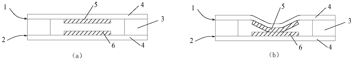
[0014] Such as figure 1 As shown, the traditional membrane switch includes an upper conductive layer 1, a lower conductive layer 2 and an insulating layer 3 between them. The upper conductive layer 1 and the lower conductive layer 2 have the same structure, and both the upper and lower conductive layers are provided with conductive lines. Layer 4 and the trigger part located on the conductive circuit layer 4, wherein the trigger part of the upper conductive layer 1 is connected to the positive electrode as the positive electrode trigger part 5, and the trigger part of the lower conductive layer 2 is connected to the negative electrode as the negative electrode trigger part 6. When not conducting, the positive trigger part 5 is separated from the negative trigger part 6, and the membrane switch is pressed, the upper conductive layer 1 is deform...


PUM


Abstract

The invention discloses a membrane switch. The membrane switch comprises an upper electric-conduction layer, a lower electric-conduction layer and an insulating layer located between the upper electric-conduction layer and the lower electric-conduction layer, wherein one of the upper electric-conduction layer and the lower electric-conduction layer includes an electric-conduction circuit layer as well as a positive pole triggering part and a negative pole triggering part which are arranged on the electric-conduction circuit layer, and the other electric-conduction layer includes a first base material layer and an electric conductor which is arranged on the first base material layer and is in conduction with the positive pole triggering part and the negative pole triggering part. According to the membrane switch of the invention, the positive pole triggering part and the negative pole triggering part are simultaneously arranged on the upper electric-conduction layer or the lower electric-conduction layer, and the corresponding upper electric-conduction layer or the lower electric-conduction layer is provided with the electric conductor with an electric-conduction function. When the membrane switch is pressed, the electric conductor simultaneously contacts with the positive pole triggering part and the negative pole triggering part, a positive pole and a negative pole are conducted, and the switch is switched on. According to the membrane of the invention, only one electric-conduction circuit layer is needed to be arranged on the layer which is provided with the positive pole triggering part and the negative pole triggering part, and therefore, compared with a traditional membrane switch, the membrane switch of the invention has the advantages of simple process and high production efficiency; and just a single circuit layer is adopted, so that production cost can be greatly reduced.

Description

technical field [0001] The invention relates to an electronic switch, in particular to a membrane switch. Background technique [0002] The existing membrane switch adopts a three-layer structure, including an upper conductive layer, an insulating layer and a lower conductive layer. Both the upper conductive layer and the lower conductive layer are provided with a trigger part. The trigger part is respectively connected to the positive pole and the negative pole. When the membrane switch is pressed, , the trigger parts on the upper and lower conductive layers are in contact, so that the positive and negative poles are turned on and the switch is turned on. The upper conductive layer and the lower conductive layer need to be provided with a circuit at the same time, so that the switch can be turned on, which makes the production process of the membrane switch complicated and the cost high. [0003] Moreover, the existing circuits are generally formed by printed silver wires,...

Claims


Application Information

Patent Timeline
Patent Type & Authority Patents(China)
IPC IPC(8): H01H13/704H01H13/807
CPCH01H13/704H01H13/807H01H2203/056H01H2205/016
Inventor 邹伟民
Owner JIANGSU TRANSIMAGE TECH CO LTD
Why Eureka
Try Eureka