Anti-corner-bending-cracking die

A corner and mold technology, applied in the field of product bending, can solve the problems of increasing the number of mold repairs, product appearance inspection, difficult molding, and increasing the risk of product failure.

Pending Publication Date: 2021-04-06
LEMTECH PRECISION MATERIAL (CHINA) CO LTD
View PDF0 Cites 0 Cited by
  • Summary
  • Abstract
  • Description
  • Claims
  • Application Information

AI Technical Summary

Problems solved by technology

[0002] For products with 90° bending and hemming with a material thickness greater than 2.0mm, the existing processing molds are prone to cracking and difficult to form when producing products
The existing processing method is to ask the customer to reduce the hemming height on the bending edge to less than twice the material thickness, and then open the hemming angle after the height is reduced, and then use the plastic method to meet the customer's requirements. This method is only suitable for relatively Short wrapping and less than twice the material thickness, this method still has the risk of cracking, increases the risk of defective products, increases the number of mold repairs and the appearance inspection of the product, and increases the cost, so it is urgent to improve this kind of wrapping Edge process and forming structure

Method used


Image

  • Anti-corner-bending-cracking die
  • Anti-corner-bending-cracking die
  • Anti-corner-bending-cracking die

Examples


Embodiment Construction

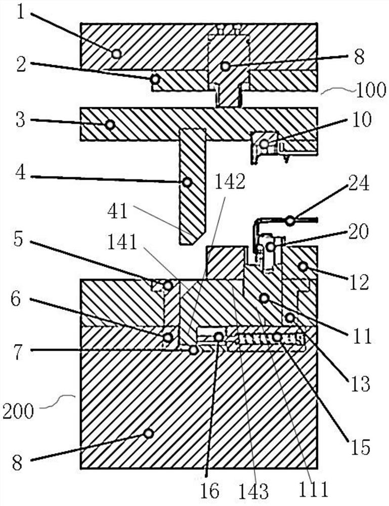
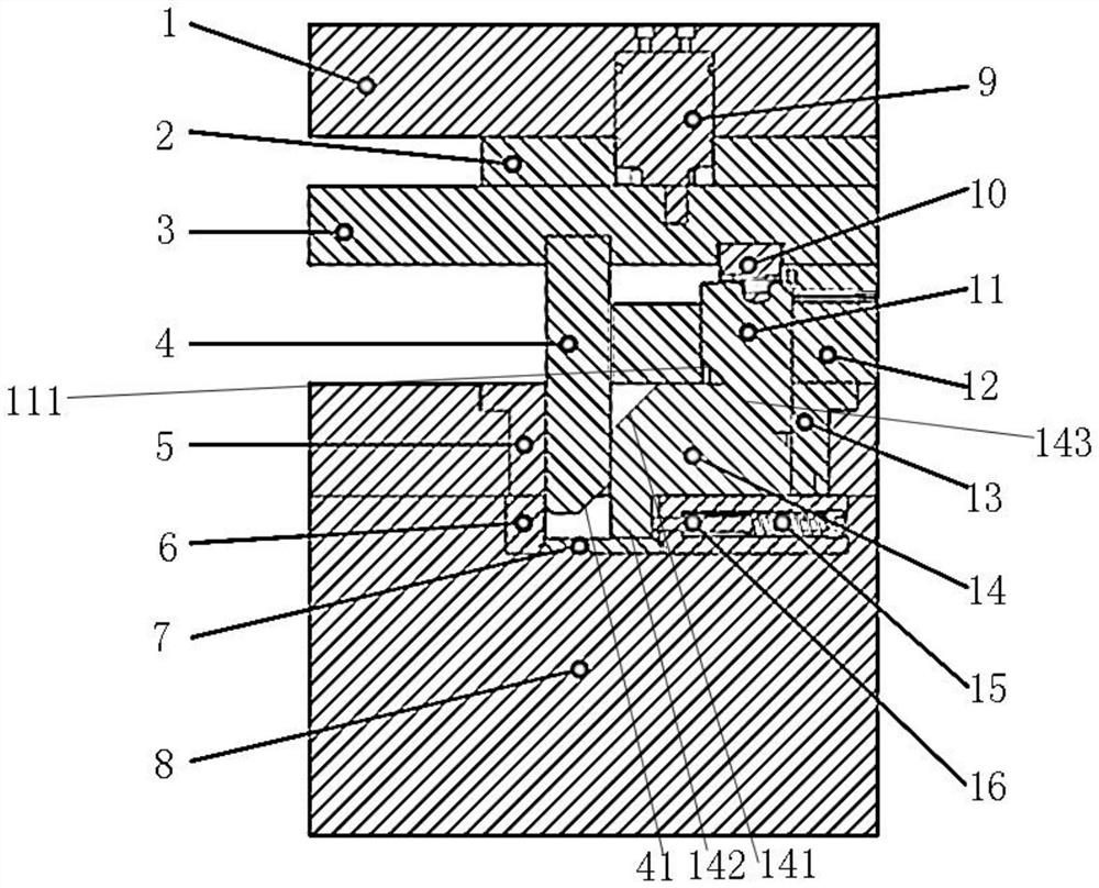
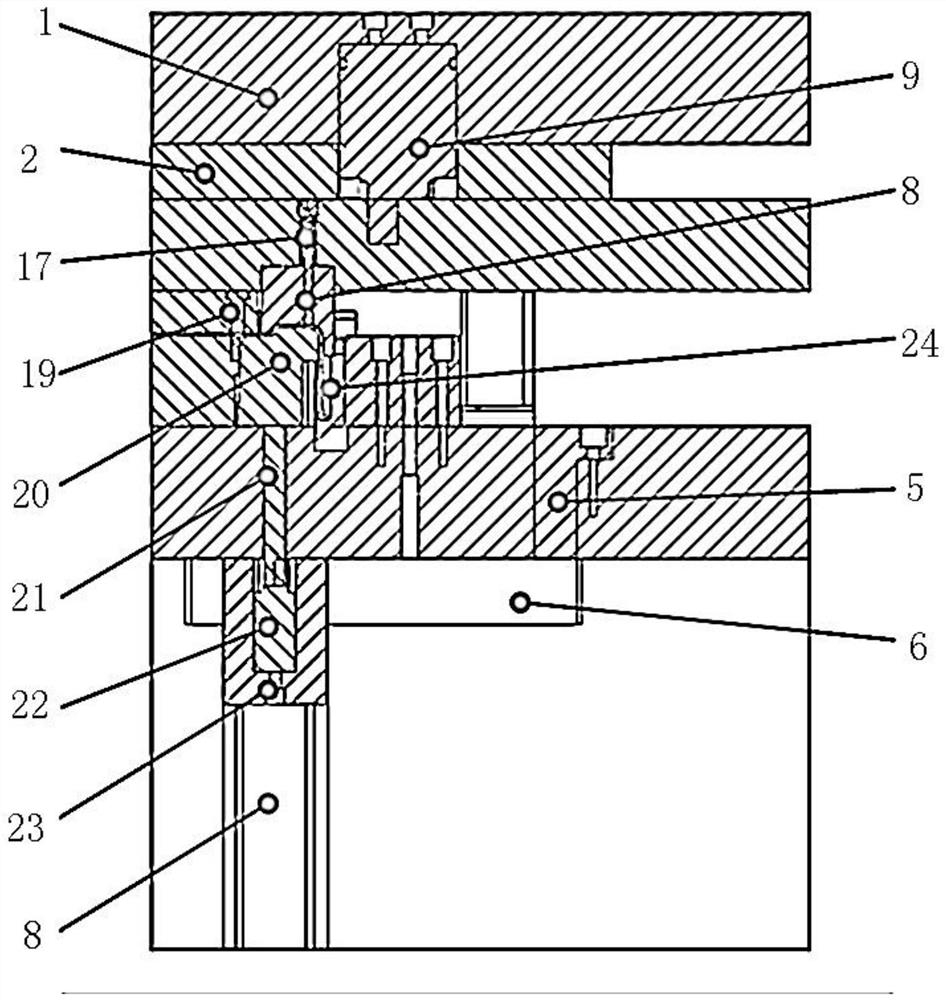
[0021] Anti-corner bending cracking die, see Figure 1-Figure 5 : It comprises upper mold part 100, lower mold part 200, upper mold part 100 comprises upper mold base 1, splint 2, large stripping plate 3, forming inserting knife 4, upper mold pressing material into block 10, the lower surface of upper mold base 1 A splint 2 is arranged, and a first nitrogen spring 9 is fixed on the upper mold base 1. The lower end of the first nitrogen spring 9 passes through the splint 2 and then connects to the upper installation groove of the large release plate 3, and the lower surface of the large release plate 3 is fixed respectively. There is a downwardly convex forming insert 4, a downwardly convex upper die press-in block 10;

[0022] The lower mold part 200 includes a lower mold base 25 and a pad 8, the lower mold base 25 is fixed on the upper surface of the pad 8, and the overall area of ​​the lower mold base 25 and the pad 8 corresponds to the shape of the forming insert 4 and the ...


PUM


Abstract

The invention provides an anti-corner-bending-cracking die. The anti-corner-bending-cracking die can meet the requirement for the height of a covered edge of a product without affecting strength of the product. The anti-corner-bending-cracking die comprises an upper die part and a lower die part, wherein the upper die part comprises an upper die base, a clamping plate, a large stripper plate, a forming slotting tool and an upper die pressing-in block, the clamping plate is arranged on the lower surface of the upper die base, a first nitrogen spring is fixedly arranged on the upper die base, the lower end of the first nitrogen spring penetrates through the clamping plate and then is connected with an upper mounting groove of the large stripper plate, and the lower surface of the large stripper plate is fixedly provided with a downwards-protruding forming slotting tool and a downwards-protruding upper die pressing-in block; the lower die part comprises a lower die base and a foot pad, the lower die base is fixedly installed on the upper surface of the foot pad, an overall area of the lower die base and the foot pad corresponds to the forming slotting tool, an inner groove is formed in the area of the upper die pressing-in block, and a slotting tool leaning tool, a wear-resisting fixing block, a driving block and a punch wear-resisting guide plate are arranged in the inner groove.

Description

technical field [0001] The invention relates to the technical field of product bending, in particular to an anti-corner bending cracking mold. Background technique [0002] For 90°bending and hemming products with a material thickness greater than 2.0mm, the existing processing molds are prone to cracking and difficult to shape when producing products. The existing processing method is to ask the customer to reduce the hemming height on the bending edge to less than twice the material thickness, and then open the hemming angle after the height is reduced, and then use the plastic method to meet the customer's requirements. This method is only suitable for relatively Short wrapping and less than twice the material thickness, this method still has the risk of cracking, increases the risk of defective products, increases the number of mold repairs and the appearance inspection of the product, and increases the cost, so it is urgent to improve this kind of wrapping Edge technol...

Claims


Application Information

Patent Timeline
Patent Type & Authority Applications(China)
IPC IPC(8): B21D37/10
CPCB21D37/10
Inventor 徐党新张亮康世杰杨加军黄杰李桂勤
Owner LEMTECH PRECISION MATERIAL (CHINA) CO LTD
Why Eureka
Try Eureka