Substrate connector

A substrate connector and substrate technology, applied in connection, fixed connection, coupling device, etc., can solve problems such as complex structure, reduced connection strength, and reduced rigidity of contacts

Active Publication Date: 2016-06-08
가부시키가이샤타케우치기쥬쯔켄큐쇼
View PDF8 Cites 5 Cited by
  • Summary
  • Abstract
  • Description
  • Claims
  • Application Information

AI Technical Summary

Problems solved by technology

In this regard, since the substrate connector of Patent Document 1 has a structure in which the spring piece portion of the female header contact is flexed in a direction perpendicular to the protruding direction relative to the insertion portion of the pin header contact, it is in contact with the insertion portion of the pin header contact. The size in the cross direction increases, which is not conducive to the realization of narrow pitch
[0009] In addition, in the substrate connector of Patent Document 1, when the insertion portion of the pin header contact is inserted between the spring pieces, the first and second spring pieces are in contact with the insertion portion and are deflected, so that the third spring piece The part is pushed by the pin header, so the structure is complicated
Therefore, according to the substrate connector of Patent Document 1, it is difficult to achieve further low profile and narrow pitch
[0010] In addition, if the pitch is simply narrowed, the width of each contact will also be narrowed, and the rigidity of each contact will decrease, so there is a problem that the connection strength will decrease.

Method used


Image

  • Substrate connector
  • Substrate connector
  • Substrate connector

Examples


Embodiment Construction

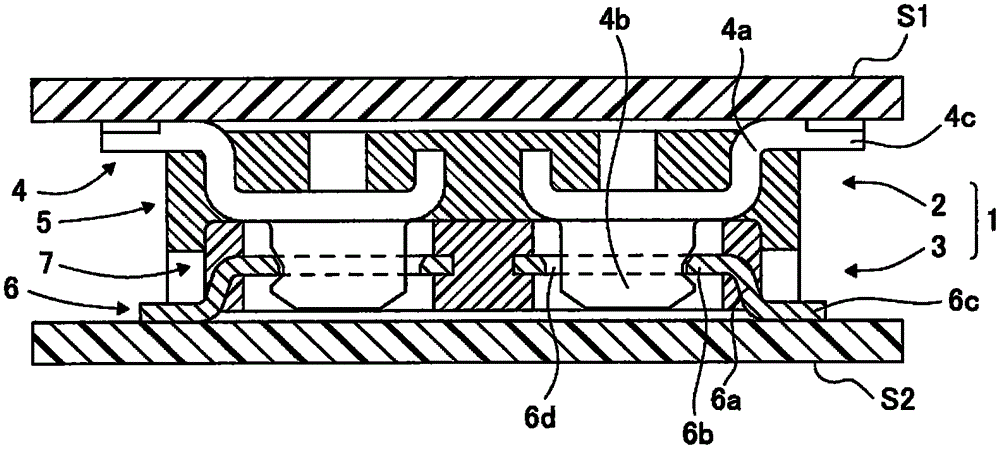
[0082] Such as figure 1 As shown, the board connector 1 of the first embodiment of the present invention is a board connector for connecting circuit boards S1 and S2. The substrate connector 1 is composed of a pin header 2 and a female header 3. The pin header 2 includes a metal pin header contact 4 and a pin header body 5 made of insulating synthetic resin.

[0083] The female header 3 also includes a female header contact 6 made of metal and a header body 7 made of insulating synthetic resin. in figure 1 In the state shown, the pin header contact 4 is in contact with the female header contact 6, and the circuit substrates S1 and S2 are electrically connected to each other.

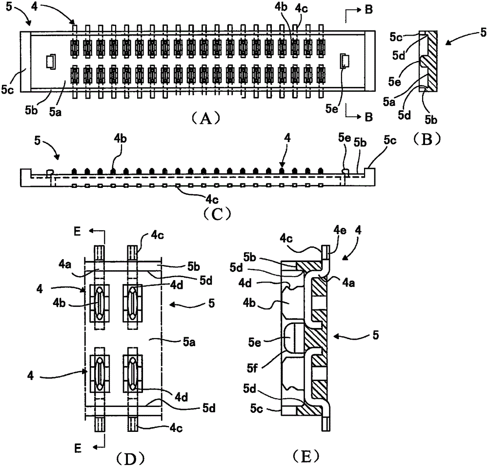
[0084] figure 2 A is a plan view of pin 2. A plurality of pin header contacts 4 are arranged side by side in the longitudinal direction of the pin header body 5. In addition, the plurality of pin header contacts 4 are arranged in the width direction of the pin header body 5 (in the figure 2 In A, the ver...


PUM


Abstract

The present invention provides a substrate connector capable of achieving low profile and narrow gap and high in connection strength. The substrate connector (1) includes a pin header (2) having a plurality of pin header contact members (4), and a female header (3) having a plurality of female header contact members (6). Each of the female header contact members (4) includes a pin-header-side contact part (4b). The female header contact members (6) are provided with female-header-side contact parts (6b) having a long ring shape. The pin-header-side contact parts (4b) are pressed into female-header-side connecting parts (6c) having a long ring shape, and are coupled through a coupling part (4) to achieve a high connection strength. The pin header (2) and the female header (3) can be disassembled through rotating around a carrying part (5d) of a pin header main body (5) and a side edge (7b) of a female header main body (7).

Description

Technical field [0001] The present invention relates to a board connector that connects circuit boards to each other and a contact for electronic devices including the board connector. Background technique [0002] Conventionally, as a board connector that electrically connects circuit boards such as printed wiring boards to each other, it is known to have a header having a plurality of header contacts and a plurality of headers respectively connected to each header contact. The board connector of the pin header of the pin contact (for example, refer to Patent Document 1). [0003] In the substrate connector of Patent Document 1, the pin header contact includes a plurality of columnar insertion portions protruding toward the mother row side. In addition, the female header contact includes first to third leaf spring portions that respectively contact the insertion portion from a direction orthogonal to the protrusion direction of the insertion portion. In addition, the pin header ...

Claims


Application Information

Patent Timeline
Patent Type & Authority Applications(China)
IPC IPC(8): H01R12/51H01R12/58H01R12/71
CPCH01R12/51H01R12/58H01R12/71
Inventor 竹内忍
Owner 가부시키가이샤타케우치기쥬쯔켄큐쇼
Why Eureka
Try Eureka