Direct current breaker

A DC circuit breaker and branch circuit technology, which is applied in circuit devices, power transmission AC networks, emergency protection circuit devices, etc., can solve the problems of a large number of MMC sub-modules and cumbersome installation, achieve rapid segmentation of DC lines, and simplify design. structure, the effect of saving busbar resources

Inactive Publication Date: 2016-06-08
XJ ELECTRIC +2
View PDF5 Cites 13 Cited by
  • Summary
  • Abstract
  • Description
  • Claims
  • Application Information

AI Technical Summary

Problems solved by technology

[0004] The purpose of the present invention is to overcome the deficiencies of the prior art, and propose a DC circuit breaker to solve the technical prob

Method used


Image

  • Direct current breaker
  • Direct current breaker
  • Direct current breaker

Examples


Embodiment 1

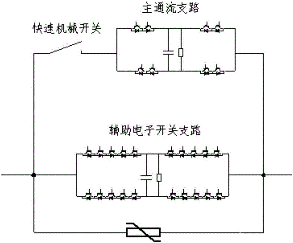
[0028] Such as figure 1 As shown, the DC circuit breaker module unit includes three branches connected in parallel, the main flow branch, the auxiliary electronic switch branch and the lightning arrester branch.

[0029] A fast mechanical switch and a converter unit module are connected in series on the main flow branch. A current breaking unit module is connected to the branch of the auxiliary electronic switch.

[0030] Both the converter unit module and the interrupter unit module are composed of full-bridge sub-modules.

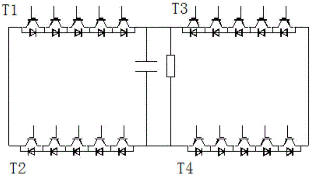
[0031] Such as figure 2 As shown, the full-bridge sub-module is composed of the first bridge arm T1, the second bridge arm T2, the third bridge arm T3, the fourth bridge arm T4, capacitors and resistors; each bridge arm is connected in series with more than two The fully controlled power switch device (IGBT is used in this embodiment).

[0032] One end of the first bridge arm is connected to one end of the second bridge arm, and the connection end is...

Embodiment 2

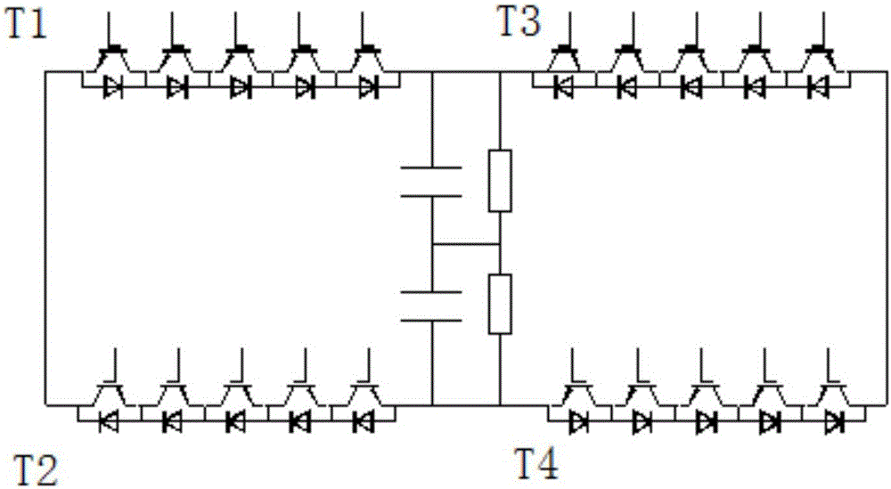
[0049] Such as Figure 4 As shown, Embodiment 2 introduces another DC circuit breaker, the difference from "A DC circuit breaker Embodiment 1" is that in Embodiment 2 only the full bridge in Embodiment 1 is used in the converter unit The form of the module, however, the cut-off unit adopts the mode that several full-bridge MMC sub-modules or half-bridge MMC sub-modules are connected in series, or the form of sampling full-bridge MMC sub-modules and half-bridge MMC sub-modules is mixed in series, even in the prior art other topological forms.

[0050] The full-bridge MMC sub-module is mainly composed of 4 IGBTs, bypass switches and capacitors. The four IGBTs are respectively the first IGBT, the second IGBT, the third IGBT and the fourth IGBT. Wherein, the anode of the capacitor is connected to the collector of the first IGBT and the collector of the third IGBT, the cathode of the capacitor is connected to the transmitter of the second IGBT and the transmitter of the fourth IG...

Embodiment 3

[0055] Such as Figure 5 As shown, the difference from "A DC Circuit Breaker Embodiment 1" is that in Embodiment 2, only the form of the full-bridge sub-module in Embodiment 1 is used in the current breaking unit, but the converter unit adopts several full-bridge MMC sub-modules or half-bridge MMC sub-modules are connected in series, or sampling full-bridge MMC sub-modules and half-bridge MMC sub-modules are mixed in series, or even other topological forms in the prior art.

[0056] The structures of the full-bridge MMC sub-module and the half-bridge MMC sub-module have been described in Embodiment 2, so no further details are given here


PUM


Abstract

The invention relates to a direct current breaker. The direct current breaker comprises a main current-passing branch, an assistant electronic switch branch and a lightning arrester branch. A mechanical switch and a current conversion unit are connected to the main current-passing branch in series, and a current cutoff unit is connected to the assistant electronic switch branch. The direct current breaker is characterized in that the current conversion unit and the current cutoff unit are each composed of a full-bridge submodule, wherein two or more full-control type power switching devices are connected to each bridge arm of the full-bridge submodule in series, and the numbers of the full-control type power switching devices connected to the bridge arms of the full-bridge submodule are equal. The invention further provides two other direct current breakers. In one other direct current breaker, only a current conversion unit is composed of a full-bridge submodule; in the other direct current breaker, only a current cutoff unit is composed of a full-bridge submodule. According to the direct current breaker, the design structure is greatly simplified, busbar resources are saved, manufacturing cost is reduced, and demounting and mounting are convenient.

Description

technical field [0001] The invention belongs to a direct current circuit breaker and belongs to the technical field of high voltage direct current transmission. Background technique [0002] At present, the topology of high-voltage DC circuit breakers mainly consists of forward and reverse series structure IGBT modules and single-stage H-bridge structure IGBT modules connected in series, and a high-voltage fast mechanical switch is configured outside. When the DC circuit breaker disconnects the DC current, a high DC transient voltage will be generated at both ends of the circuit breaker. Therefore, many IGBT modules need to be connected in series in the transfer branch of the DC circuit breaker, and the fast mechanical switch is required to withstand high switching off. Therefore, the DC circuit breaker is bulky and expensive. At the same time, the requirements for fast mechanical switches are very high, and the design is extremely difficult. [0003] The application number...

Claims


Application Information

Patent Timeline
IPC IPC(8): H02H3/00H02J3/36
CPCY02E60/60H02H3/00H02J3/36
Inventor 范彩云何青连洪波张志刚胡秋玲
Owner XJ ELECTRIC
Why Eureka
Try Eureka