Moulding unit for the manufacture of containers comprising compensation gripper

A molding and fixture technology, used in household components, applications, household appliances, etc., can solve problems such as large mechanical stress, and achieve the effect of good energy efficiency

Active Publication Date: 2016-06-08
SIDEL PARTICIPATIONS SAS
View PDF8 Cites 3 Cited by
  • Summary
  • Abstract
  • Description
  • Claims
  • Application Information

AI Technical Summary

Problems solved by technology

[0049] The compensation chamber also causes high mechanical stress both on the locking part and on the mold holder of the molding unit

Method used


Image

  • Moulding unit for the manufacture of containers comprising compensation gripper
  • Moulding unit for the manufacture of containers comprising compensation gripper
  • Moulding unit for the manufacture of containers comprising compensation gripper

Examples


Embodiment Construction

[0098] Conventionally, the longitudinal and transverse directions are determined relative to the mold base in a fixed manner such that the open or closed position is not affected by these orientations.

[0099] Also, without limitation, the expressions "front" and "rear" are used with reference to the longitudinal direction, "up" and "bottom" or "high" and "low" with reference to the vertical direction, and finally "left", "right" with reference to the landscape direction And "inside" and "outside".

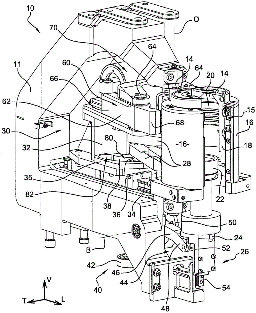
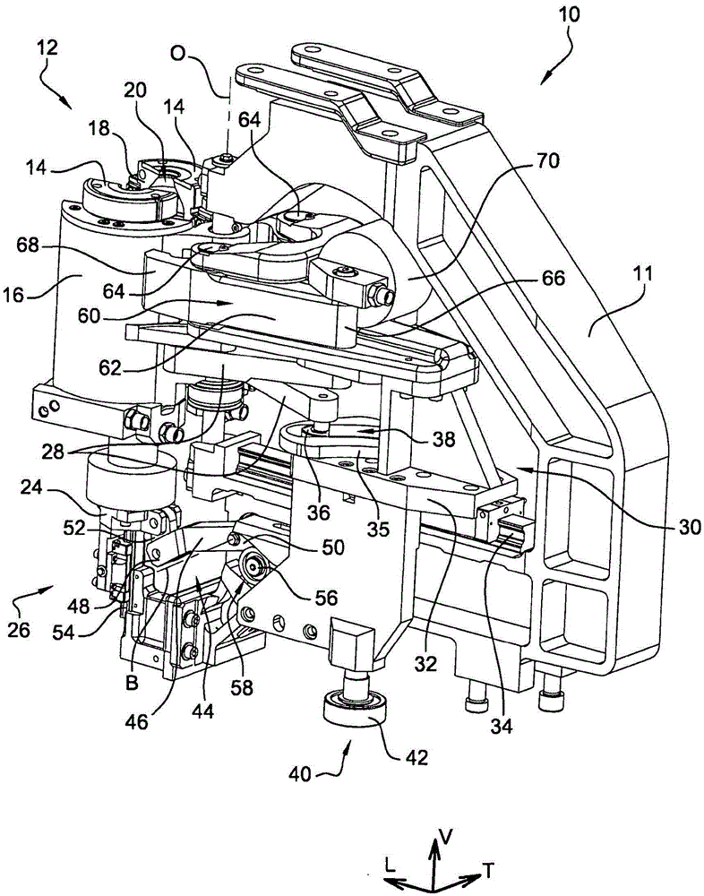
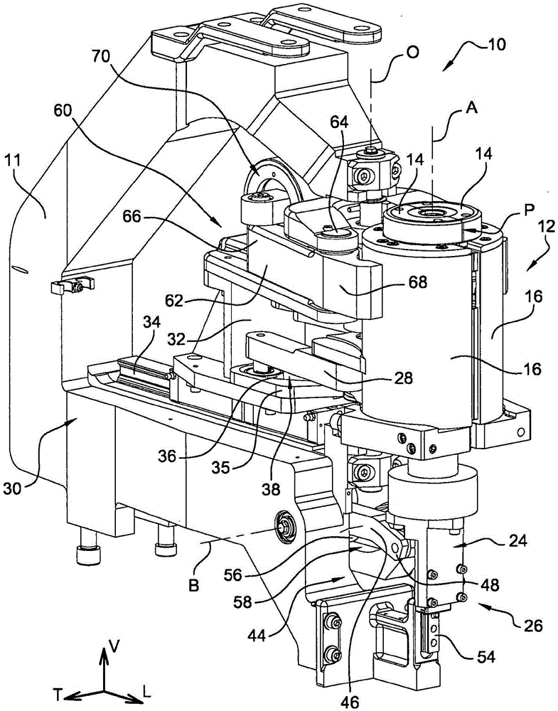
[0100] Figure 1-4 An embodiment of a molding unit 10 for producing containers from preforms of thermoplastic material is shown in FIG.

[0101] The molding unit 10 according to this embodiment is more particularly intended to be mounted on a container making machine (not shown) of the rotary type.

[0102] The molding unit 10 comprises a frame 11 mounted so as to be fixedly connected via the frame 11 to the circular conveyor of the machine, which is driven to rotate around a ver...


PUM


Abstract

The present invention relates to a moulding unit (10) for the manufacture of containers from preforms made of thermoplastic, said moulding unit (10) being characterized in that it comprises compensating means which are formed of at least one gripper (60) which acts on mould carriers (16) that carry the mould (12) of the unit (10) in order to clamp them against one another when the moulding unit (10) is in the closed position and to apply a compensating force that tends to clamp together moulding elements (14) of the mould (12) at said parting line (P) and opposes the forces that a pressurised fluid applies to the moulding elements (14) when a container is being moulded from a preform.

Description

technical field [0001] The invention relates to a molding unit for manufacturing containers comprising compensating clamps. [0002] The invention more particularly relates to a molding unit for producing containers from preforms made of thermoplastic material, said molding unit comprising at least: [0003] - a frame carrying a mold comprising at least two molding elements each mounted in an associated mold holder; [0004] - at least one of said mold seats is mounted rotatably relative to the other mold seat about a vertical axis of rotation between an open position of the mould, and a closed position in which said molding elements pass through the respective The abutment faces engage against each other and together define a mold cavity, the abutment faces defining a longitudinally oriented vertical joint plane; [0005] - forming parts for introducing at least one pressurized fluid inside the preform for molding the corresponding container in the mold cavity; [0006] - ...

Claims


Application Information

Patent Timeline
Patent Type & Authority Applications(China)
IPC IPC(8): B29C49/56
CPCB29L2031/7158B29C49/06B29C49/56B29C2049/4892B29C2049/563B29C49/5602B29C49/561B29C49/5612B29C2049/5633B29C2049/5635B29C2949/0715B29C49/30
Inventor J·米歇尔F·勒孔特P·安德勒M·多迪尼
Owner SIDEL PARTICIPATIONS SAS
Why Eureka
Try Eureka