
Composite heat shield for spacecraft reentry body

A technology of spacecraft and heat protection layer, which is applied in the direction of aerospace vehicle heat protection devices, aerospace safety/emergency devices, etc., and can solve the requirements that cannot meet the performance requirements of spacecraft re-entry bodies, limited space body shape, and heat insulation requirements Advanced problems, to achieve the effect of improving thermal insulation performance, reducing thermal conductivity and temperature conductivity, and meeting heat protection requirements

Inactive Publication Date: 2011-02-16
北京玻钢院复合材料有限公司
View PDF0 Cites 22 Cited by
  • Summary
  • Abstract
  • Description
  • Claims
  • Application Information

AI Technical Summary

Benefits of technology

This patented technology describes an alternative way to make better ways to prevent fires when entering spacesuits during flight operations. By incorporating certain special features or compositions within these layers, they improve their ability to resist fire damage without compromising its effectiveness at other temperatures. These techniques help protect against flammable liquids such as fuel oil and gasoline inside the aircraft's cabin interior. Additionally, there may include different methods used to create the necessary ingredients needed for effective manufacturing processes like injection molded thermosets (RIM)). Overall, this innovative design helps achieve desired results through improving the overall properties of the air conditioner system itself.

Problems solved by technology

This patented describes different ways that space craft parts are protected from damage caused during rapid changes between atmospheric conditions or after being returned into an airspace environment without losing their effectiveness over long periods of times. One method uses special materials called fibrofibreglass compositions made up of layers of silica sandwiching one another. These techniques aim to improve durability while still maintaining good electrical conductivity properties.

Method used


Image

  • Composite heat shield for spacecraft reentry body
  • Composite heat shield for spacecraft reentry body
  • Composite heat shield for spacecraft reentry body

Examples


Embodiment 1

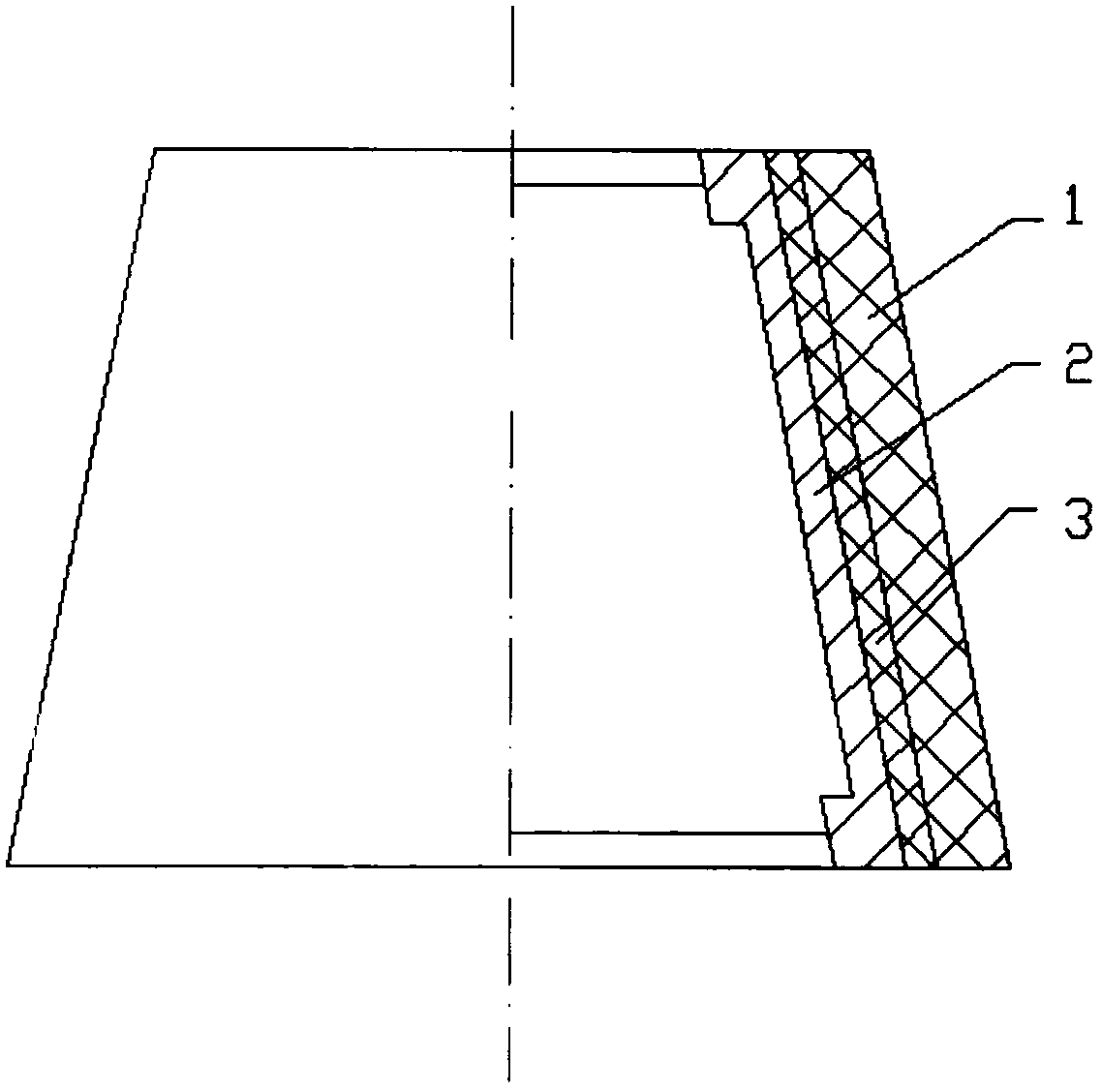
[0058] The composite heat-proof layer of the spacecraft re-entry body in this embodiment includes an ablation layer 1 and a heat-insulation layer 3 added to the ablation layer 1, and the heat-insulation layer 3 adopts a new type of glass fiber reinforced plastic material with hollow glass microspheres , the ablation layer 1 is made of high silica cloth treated with phenolic resin.

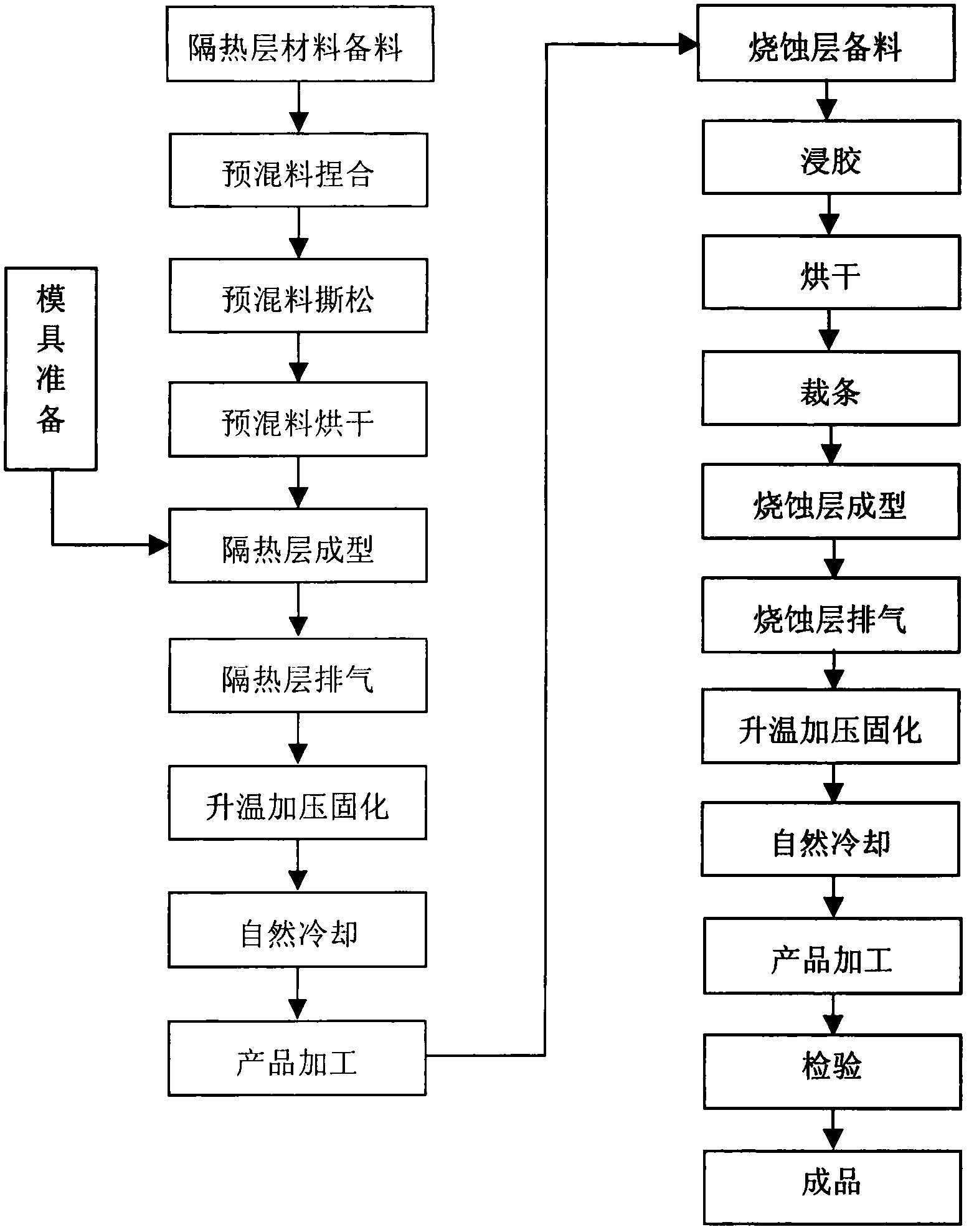
[0059] image 3 The forming process flow of the composite heat-proof layer of the spacecraft re-entry body of the present invention is two layers, and the process is as follows:

[0060] The heat insulation layer 3 is formed by adding a premixed material with a low thermal conductivity function to form a glass fiber reinforced plastic molding method

[0061] ① Mold preparation, prefabrication of a mold that matches the shape of the spacecraft re-entry body;

[0062] ②Insulation layer preparation

[0063] The high-strength chopped glass fiber yarn, resin and hollow glass microspheres are accordin...

Embodiment 2

[0089] The composite heat-proof layer for spacecraft re-entry in this embodiment is characterized in that: the ablation layer 1 is made of phenolic resin pre-impregnated adhesive tape, and all other steps are the same as in Embodiment 1, only the premix formula is different. The forming process of the composite heat-proof layer is the same as that in Embodiment 1. No longer.

Embodiment 3

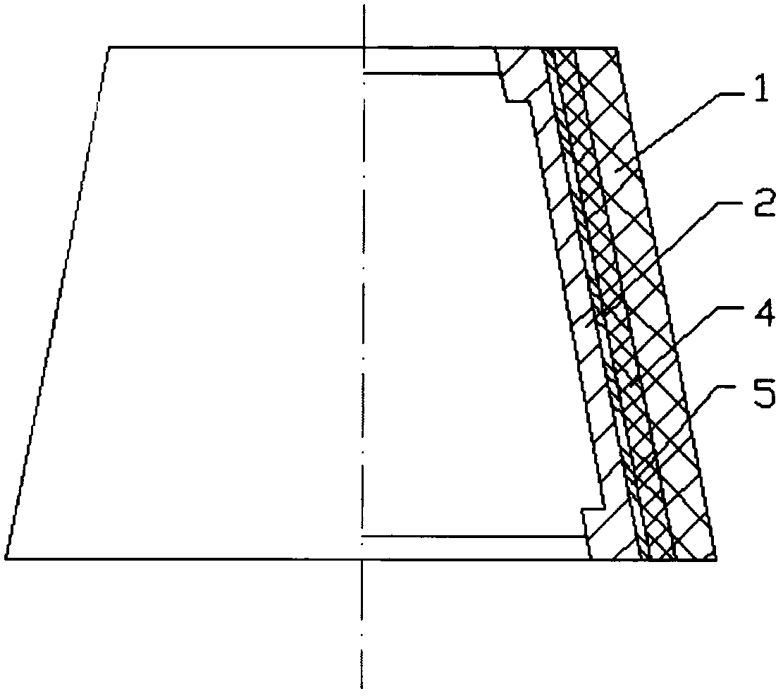
[0091] The composite heat-proof layer of the spacecraft re-entry body in this embodiment is characterized in that: the heat-insulating layer 3 is composed of an inner layer 4 and an outer layer 5, and the inner layer 4 adopts ordinary glass fiber reinforced plastic prepared by a conventional method, and the outer layer Layer 5 is a thermal insulation material, and the thermal insulation material is EPDM film. The ablation layer 1 is the ablation layer of Embodiment 1, and the material is high silica cloth treated with phenolic resin.

[0092] Figure 4 The forming process flow of the composite heat-proof layer of the spacecraft re-entry body of the present invention is three layers, and the process is as follows:

[0093] The inner layer 4 and the outer layer 5 of the heat insulation layer constitute the forming method of the heat insulation layer

[0094] ① Mold preparation;

[0095] ②Materials for the heat insulation layer are prepared. The inner layer 4 is made of glass c...


PUM

PropertyMeasurementUnit
Thermal conductivityaaaaaaaaaa

Abstract

The invention discloses a composite heat-proof layer scheme for a spacecraft reentry body, belonging to the technical field of spacecraft heat protection. The purpose of the utility model is to provide a novel composite structure heat-proof layer capable of coping with severe heat environment. The technical scheme is as follows: a composite heat-proof layer for a spacecraft reentry body, which is characterized in that it is composed of a heat-insulating layer and an ablation layer, and the ablation layer is formed by winding fiber reinforced material impregnated with phenolic resin. A method for forming a heat-resistant layer of a composite structure, which is characterized in that it includes the following steps: forming the heat-insulating layer, compounding the formed heat-insulating layer with an ablation layer, curing the formed composite-structured heat-resistant layer under high temperature pressure, and machining forming. It achieves the purpose of reducing the thermal conductivity and temperature conductivity of the heat-resistant component. The component is light in weight and has excellent performance, which can meet the requirements for improving the heat-resistant performance of various spacecraft reentry bodies at present, and is suitable for industrial production.

Description


Claims


Application Information

Patent Timeline
Owner 北京玻钢院复合材料有限公司
Learn More