
A landing probe soft landing mechanism buffer

A technology of buffers and detectors, which is applied in the direction of aerospace vehicle landing devices, elastic shock absorbers, and systems for aerospace vehicles to return to the earth's atmosphere. It can solve the problems of insufficient energy absorption, sensitivity to temperature changes, and difficult applications. problems, to achieve the effect of ensuring safe landing, stable performance and compact size

Active Publication Date: 2012-02-22
BEIJING INST OF SPACECRAFT SYST ENG
View PDF0 Cites 5 Cited by
  • Summary
  • Abstract
  • Description
  • Claims
  • Application Information

AI Technical Summary

Problems solved by technology

The advantage of the hydraulic damping method is that it can be used multiple times, but this method is sensitive to temperature changes, and it is difficult to apply in space environments and has low reliability
Although the spring damping method has good cushioning performance, it cannot fully absorb energy and has the possibility of secondary rebound
The cushioning performance of the thin-walled metal tube expansion deformation method is slightly affected by the environment such as temperature, but the cushioning force has obvious fluctuations in the transition section of the two metal tubes
The cushioning performance of the metal foam crushing deformation method is less affected by the environment such as temperature, and the processing technology is simple, but generally requires a larger space size. In addition to the advantages similar to the foam metal crushing deformation method, the aluminum honeycomb material crushing deformation method also has low cost. Lower, larger compression ratio, easy to meet the advantages of various cushioning requirements, the disadvantage is that when the compression ratio is large, irregular crushing may occur, resulting in a sudden change in the cushioning force

Method used


Image

  • A landing probe soft landing mechanism buffer
  • A landing probe soft landing mechanism buffer
  • A landing probe soft landing mechanism buffer

Examples


Embodiment Construction

[0016] The specific implementation process of the present invention will be further described below in conjunction with the accompanying drawings:

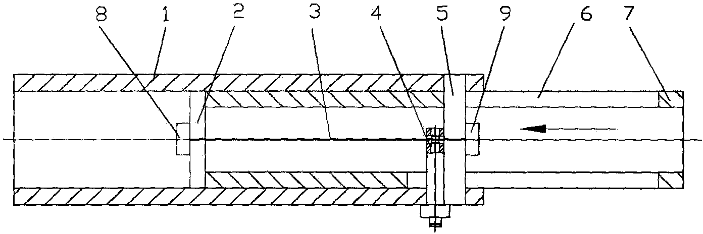
[0017] Such as figure 1 As shown, the present invention is a piston structure, which mainly includes an outer cylinder 1, a support plate 2, a metal tie rod 3, a cutter 4, a support rod 5, a "1" groove 6, an inner cylinder 7, a nut 8 and a nut 9.

[0018] The support plate 2 is integrated with the inner cylinder 7, and the inner cylinder 7 has a "1" groove 6, the support rod 5 passes through the "1" groove and is connected with the outer cylinder 1, and the two ends of the pull rod 3 are threaded , the nut 8 and the nut 9 are tightened between the support rod 5 and the support plate 2, and the cutter 4 is connected with the outer cylinder 1 as a whole. When the soft landing mechanism works, the inner cylinder 7 moves in the direction of the arrow, and the tie rod 3 is pulled. When the tension reaches its yield limit, the metal ti...


PUM


Abstract

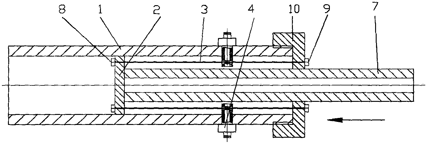
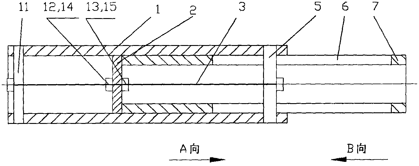
The invention provides a soft landing mechanism buffer for a landing probe, which is used for buffering the impact of the spacecraft. The invention is mainly composed of an outer cylinder, a metal tie rod, an inner cylinder, a cutter, a support plate, a support rod, etc., adopts a piston structure, and tightens the metal pull rod between the support rod and the support plate, and the metal pull rod can be located inside The center of the barrel or around the outer wall of the inner barrel. Another structure of the present invention is a buffer structure with bidirectional buffer function. The invention absorbs the impact energy through the yield deformation of the metal tie rod, is less affected by the space environment, has stable performance, reliable operation and compact volume.

Description

technical field [0001] The invention relates to a soft landing mechanism buffer for a landing probe. Background technique [0002] In order to ensure the safe landing of the spacecraft on the moon or other planets, a soft landing mechanism is generally required to absorb the impact of the spacecraft at the moment of landing, so as to ensure the safety of the instruments, equipment or personnel on the spacecraft. There are many methods for impact buffering, such as hydraulic damping method, spring damping method, thin-walled metal tube expansion deformation method, foam metal crush deformation method and aluminum honeycomb material crush deformation method. The advantage of the hydraulic damping method is that it can be used many times, but this method is sensitive to temperature changes, and its application in space environments is difficult and has low reliability. Although the spring damping method has good cushioning performance, it cannot fully absorb energy and has the...

Claims


Application Information

Patent Timeline
IPC IPC(8): F16F7/12B64G1/62
Inventor 杨建中满剑锋曾福明商红军
Owner BEIJING INST OF SPACECRAFT SYST ENG
Learn More