Eureka AIR delivers breakthrough ideas for toughest innovation challenges, trusted by R&D personnel around the world.

Quantitative uniform grouting machine

A grouting machine, uniform technology, applied in the direction of supply device, manufacturing tool, etc., can solve problems such as poor fluidity and change of slurry

Active Publication Date: 2016-06-15
南通舜腾纺织品有限公司
View PDF6 Cites 8 Cited by
  • Summary
  • Abstract
  • Description
  • Claims
  • Application Information

AI Technical Summary

Problems solved by technology

[0003] Usually, there are one or two outlets in the mixing tank, and the mixing tank uses a ball valve to control the outlet, but because the pressure at the outlet will decrease with the slurry in the mixing tank, the outlet The slurry flow at the location will change with the slurry in the mixing tank; in addition, there are multiple cavities in one mold, and the length of the cavity is generally 2.5~3.2 meters, but the width is only 90mm. Therefore, The fluidity of slurry is poor

Method used


Image

  • Quantitative uniform grouting machine
  • Quantitative uniform grouting machine
  • Quantitative uniform grouting machine

Examples


Embodiment Construction

[0028] In order to make the object, technical solution and advantages of the present invention clearer, the present invention will be further described in detail below in conjunction with the accompanying drawings. It is only stated here that the words for directions such as up, down, left, right, front, back, inside, and outside that appear or will appear in the text of the present invention are only based on the accompanying drawings of the present invention, and are not specific to the present invention. limited.

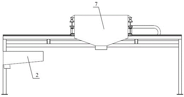
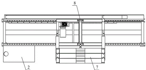
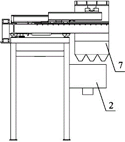
[0029] see Figure 1~Figure 6 , Figure 1~Figure 6 It shows a structural schematic diagram of a quantitative and uniform grouting machine of the present invention, including a frame part 1, a water tank 2, a first linear guide rail 3, a translation frame 4, a motor assembly 5, a second linear guide rail 6, and equal grouting Bucket 7 and cylinder 8; The water receiving tank 2 is located at the bottom of the frame part 1, and the translation frame 4 is fixed on ...


PUM


Abstract

The invention discloses a quantitative uniform grouting machine. The quantitative uniform grouting machine comprises a rack component, a water collecting tank, first linear guide rails, a translation rack, a motor assembly, second linear guide rails, an equivalent grouting barrel and an air cylinder, wherein the motor assembly is used for driving the translation rack, and the air cylinder is used for driving the equivalent grouting barrel; the water collecting tank is arranged on the lower part of the rack component, and the translation rack is fixed to the top of the rack component by virtue of the first linear guide rails and can slide back and forth along the first linear guide rails; the motor assembly, the air cylinder and the second linear guide rails are arranged on the translation rack, and the equivalent grouting barrel is fixed to the translation rack by virtue of the second linear guide rails and can slide back and forth along the second linear guide rails; the first linear guide railsare perpendicular to the second linear guide rails. According to the quantitative uniform grouting machine, the first linear guide railsare perpendicular to the second linear guide rails, so that the equivalent grouting barrel flexibly moves, the quantitative uniform grouting machine has the advantages of simple structure, convenience in operation and strong flexibility, and a plurality of mold cavities in a mold can be quantitatively and uniformly grouted.

Description

technical field [0001] The invention relates to the field of ceramic manufacturing technology, in particular to a quantitative and uniform grouting machine. Background technique [0002] In the automatic production line of magnesite bricks, after various raw materials are fully stirred in the mixing tank, the slurry needs to be poured into the cavity of the mold. [0003] Usually, there are one or two outlets in the mixing tank, and the mixing tank uses a ball valve to control the outlet, but because the pressure at the outlet will decrease with the slurry in the mixing tank, the outlet The slurry flow at the location will change with the slurry in the mixing tank; in addition, there are multiple cavities in one mold, and the length of the cavity is generally 2.5~3.2 meters, but the width is only 90mm. Therefore, The fluidity of the slurry is poor. Then how to realize equal amount and uniform pouring of multiple cavities in the mold has become an urgent problem to be solve...

Claims


Application Information

Patent Timeline
IPC IPC(8): B28B13/02
CPCB28B13/023
Inventor 李树高吕国锋朱勇毅
Owner 南通舜腾纺织品有限公司
Why Eureka
Eureka Blog
Learn More