Semi-automatic lock for container highway transportation

A technology for road transportation and containers, which is applied in the field of semi-automatic locks for container road transportation, which can solve the problems of high risk, high labor intensity of workers, and low efficiency of manual lock operation, so as to avoid safety accidents, reduce labor intensity of workers, and save operation The effect of steps

Active Publication Date: 2016-06-15
KUSN LUCKY SEA IND
View PDF5 Cites 1 Cited by
  • Summary
  • Abstract
  • Description
  • Claims
  • Application Information

AI Technical Summary

Problems solved by technology

[0003] The technical problem to be solved by the present invention is to provide a semi-automatic lock for container road transport, which solves the problems of low operating efficiency, high labor intensity and high risk of manual locks

Method used


Image

  • Semi-automatic lock for container highway transportation
  • Semi-automatic lock for container highway transportation
  • Semi-automatic lock for container highway transportation

Examples


Embodiment 1

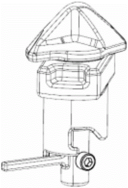
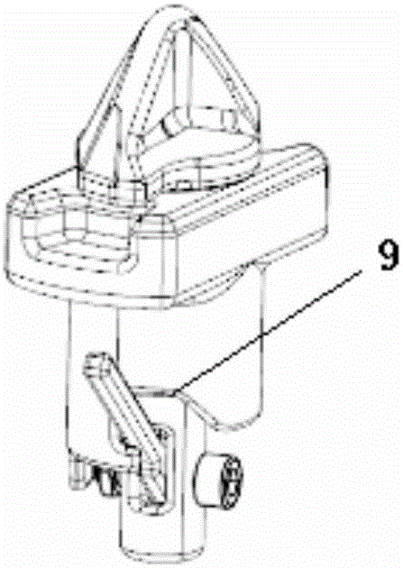
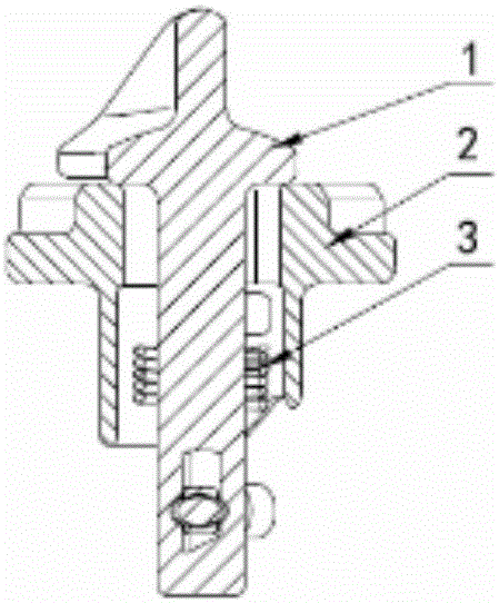
[0024] Such as Figure 1~4 As shown, a semi-automatic lock for container road transport includes a lock shaft 1, a housing 2, a spring 3 and a handle 4, wherein the upper end of the lock shaft 1 is a lock head 5, and the lower end is a rotating shaft 6, and the rotating shaft 6 is provided with a spring clip 7 in the middle, and a handle 4 is installed at the lower end of the rotating shaft 6, and the handle 4 can rotate up and down relative to the rotating shaft 6. The lock shaft 1 is installed on the housing 2, and the housing 2 There is a card slot 9 at the position corresponding to the handle 4 at the lower end, and a limit protrusion 8 is provided on one side of the card slot 9 for limiting the handle 4. The lower end of the spring clamp 7 and the rotating shaft 6 are equipped with The spring 3, the two ends of the spring 3 are respectively connected with the rotating shaft 6 and the housing 2, and is used for resetting the locking head 5 after rotating.

[0025] The low...

Embodiment 2

[0034] The operation steps when loading the container are:

[0035] 1, the present invention is installed on the car body, as Figure 8 shown;

[0036] 2. Observe each lock to make each lock in a locked state, such as figure 1 shown;

[0037] 3. Lift the container to the top of the car body, and align the corner fitting holes of the container with the lock head, such as Figure 9 shown;

[0038] 4. Drop the container, reset the lock head after rotating, and complete the loading. At this time, the container and the car body are locked together, such as Figure 10 and Figure 11 shown.

Embodiment 3

[0040] The operation steps when unloading the container are as follows:

[0041] 1. Pull the handle, put the handle in the groove of the shell, at this time the lock is opened, as Figure 12 and Figure 13 shown;

[0042] 2. Lift the container and lift it away to complete the unloading, such as Figure 14 shown;

[0043] 3. Open the handle to reset the lock, such as Figure 15 shown in preparation for the next load.


PUM


Abstract

The invention relates to a semi-automatic lock for container highway transportation. The semi-automatic lock comprises a lock shaft, a shell, a spring and a handle. A lock end is arranged at the upper end of the lock shaft, and a rotary shaft is arranged at the lower end of the lock shaft. A spring clamping position is arranged in the middle of the rotary shaft, and the handle is mounted at the lower end of the rotary shaft. The handle can vertically rotate relative to the rotary shaft. The lock shaft is mounted on the shell. A clamping groove is formed in the position, corresponding to the handle, of the lower end of the shell. A limiting convex block is arranged on one side of the clamping groove and used for limiting the handle. The spring is arranged at the position, at the lower end of the spring clamping position, of the rotary shaft. The two ends of the spring are connected with the rotary shaft and the shell and used for resetting the lock end after the lock end rotates. The semi-automatic lock has the automatic locking function, and manual operation is needed only during unlocking; and when a container is mounted on a vehicle body, the lock end can be automatically reset, no manual operation is needed, and therefore the loading efficiency is greatly improved, and meanwhile the safety accidents which happen in the container transportation process due to the fact that workers possibly forget to close the lock are avoided.

Description

technical field [0001] The invention belongs to the technical field of container road transport and semi-automatic locks, in particular to a semi-automatic lock for container road transport. Background technique [0002] When the container is transported on the road, it is necessary to fasten the container on the car body, and this fastening is realized by a lock. The locks in the prior art are all manual locks, and manual operation is required for unlocking and closing the locks, so that the loading efficiency is low, the labor intensity of the workers is also high, and it is also easy to misuse, for example, the workers forget to lock it, causing the container to be locked during transportation. accidents and losses. Therefore, a kind of semi-automatic lock for container road transportation needs to be provided to improve efficiency and ensure transportation safety. Contents of the invention [0003] The technical problem to be solved by the present invention is to pro...

Claims


Application Information

Patent Timeline
Patent Type & Authority Applications(China)
IPC IPC(8): B65D90/00
CPCB65D90/00
Inventor 刘贤兴张昱帆沈佳滨贺春标
Owner KUSN LUCKY SEA IND
Why Eureka
Try Eureka