Conveying device and method for conveying strip-shaped workpieces

A strip-shaped workpiece and conveying device technology, which is applied in the direction of conveyor objects, conveyors, transportation and packaging, etc., can solve the problems of low degree of automation, large number of workers, damaged workpieces, etc.

Active Publication Date: 2016-06-15
NINGBO MINTH AUTOMOTIVE PARTS RES&DEV CO LTD
View PDF8 Cites 4 Cited by
  • Summary
  • Abstract
  • Description
  • Claims
  • Application Information

AI Technical Summary

Problems solved by technology

[0002] Finely made strip-shaped workpieces are often used as a carrier between various processes in the production process or during storage and transportation. For example, aluminum strips or stainless steel bright strips used as automotive trim strips are generally completed manually. The strip-shaped workpieces are taken from the work platform and placed on The work of the workpiece turntable and the work of transporting the turntable requires a large number of workers and low labor efficiency, and manual picking up parts from the work platform will inevitably lead to safety accidents, and it is easy to dirty or even damage the workpiece; However, the conveying device and conveying method for conveying strip-shaped workpieces in the prior art still have a low degree of automation, a high manual operation component, and low operating efficiency.

Method used


Image

  • Conveying device and method for conveying strip-shaped workpieces
  • Conveying device and method for conveying strip-shaped workpieces
  • Conveying device and method for conveying strip-shaped workpieces

Examples


Embodiment Construction

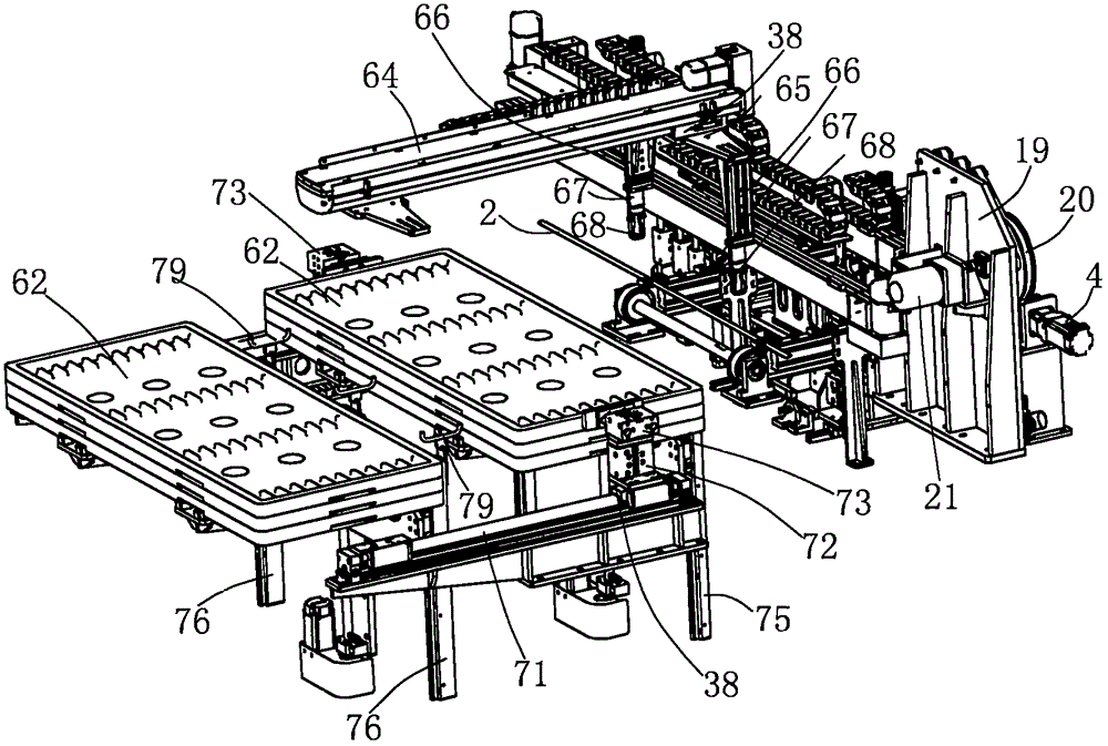
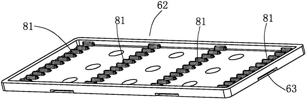
[0015] The present invention is used for the conveying device of conveying strip workpiece 2, as figure 1 , image 3 As shown, including a frame, a plurality of workpiece turnover discs 62 are configured, and the workpiece turnover discs 62 are suitable for multiple overlapping placements. Each workpiece turnover disc is suitable for storing a plurality of strip-shaped workpieces 2. The left and right sides of each workpiece turnover disc 62 are arranged Concave 63, the conveying device includes an electric cylinder 64 arranged longitudinally above the frame according to the conveying stroke, the moving block 38 of the electric cylinder 64 is fixedly connected to the moving plate 65, and the left and right sides of the moving plate 65 are respectively connected to the fifteenth cylinder 66 , the piston rods of the 2 fifteenth cylinders 66 are fixedly connected to the sixteenth cylinder 67 respectively, and a pair of rotating rods of the sixteenth cylinder 67 are respectively c...


PUM


Abstract

The invention provides a conveying device for strip-shaped workpieces. The conveying device is provided with a plurality of workpiece transfer discs (62). An electric cylinder (64) arranged above a rack in the longitudinal direction of a conveying stroke is included, and a movable block (38) of the electric cylinder (64) is fixedly connected with a movable plate (65). The lower portions of the left side and the right side of the movable plate (65) are each connected with a fifteenth air cylinder (66). Sixteenth air cylinders (67) are fixedly connected below piston rods of the two fifteenth air cylinders (66). A pair of rotary rods of the sixteenth air cylinders (67) is connected with grippers (68). A front frame (69) and a rear frame (70) for containing the workpiece transfer discs (62) are arranged at the position, below the rear portion of the electric cylinder (64), of the rear portion of the rack. Rodless air cylinders (71) are arranged on the left side and the right side of the rack by spanning the front frame (69) and the rear frame (70). A seventeenth air cylinder (72) moving vertically and an eighteenth air cylinder (73) oppositely moving in the transverse direction are arranged on movable blocks (38) of the rodless air cylinders (71) on the two sides. A convex block (74) used for being inserted into concave parts (63) of the workpiece transfer discs (62) is arranged at the end of a piston rod of the eighteenth air cylinder (73). The conveying device is high in automation degree, manual operation is not need in the process, the conveying work efficiency is high, and the conveying device is especially suitable for conveying automobile panel workpieces between operation procedures.

Description

technical field [0001] The invention relates to a conveying device and a conveying method for conveying strip-shaped workpieces, in particular to a conveying device and a conveying method for automobile decorative strip workpieces. Background technique [0002] Finely made strip-shaped workpieces are often used as a carrier between various processes in the production process or during storage and transportation. For example, aluminum strips or stainless steel bright strips used as automotive trim strips are generally completed manually. The strip-shaped workpieces are taken from the work platform and placed on The work of the workpiece turntable and the work of transporting the turntable requires a large number of workers and low labor efficiency, and manual picking up parts from the work platform will inevitably lead to safety accidents, and it is easy to dirty or even damage the workpiece; However, the conveying device and conveying method for conveying strip-shaped workpi...

Claims


Application Information

Patent Timeline
Patent Type & Authority Applications(China)
IPC IPC(8): B65G47/90B65G57/03
CPCB65G47/90B65G57/03B65G2201/0217
Inventor 陈浙东
Owner NINGBO MINTH AUTOMOTIVE PARTS RES&DEV CO LTD
Why Eureka
Try Eureka