A suction device for a vacuum feeder

A technology of vacuum feeder and suction device, which is applied in conveyors, transportation and packaging, and conveying bulk materials, etc., can solve the problems of lack of air circulation in conveying pipelines, repeated manual operations, and inability to absorb materials. Multiple manual operations, easy to use, and the effect of improving use efficiency

Active Publication Date: 2018-04-03
NINGXIA KOCEL MOLD
View PDF11 Cites 0 Cited by
  • Summary
  • Abstract
  • Description
  • Claims
  • Application Information

AI Technical Summary

Problems solved by technology

[0003] The present invention aims at the deficiency of the prior art: the powder inserted too deep blocks the material suction device, resulting in the phenomenon that the air in the conveying pipeline does not circulate and cannot absorb the material, while the insertion is too shallow, the material is easy to be sucked, and multiple manual operations are required. And developed a simple vacuum feeding machine suction device, simple structure, stable work, can solve the phenomenon of powder blocking the suction device and multiple manual operations, and can use the suction device to adjust the suction, easy to use, improve vacuum Loading machine usage efficiency

Method used


Image

  • A suction device for a vacuum feeder
  • A suction device for a vacuum feeder
  • A suction device for a vacuum feeder

Examples


Embodiment Construction

[0023] In order to enable those skilled in the art to better understand the technical solutions of the present invention, the present invention will be further described in detail below in conjunction with specific examples.

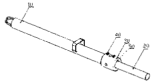
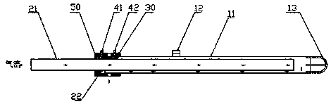
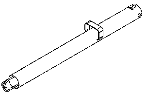
[0024] figure 1 It is the three-dimensional structural diagram of suction device of the present invention, as figure 1 As shown, the suction device of the vacuum feeder of the present invention includes an outer gun 10 , an inner gun 20 , a connecting sleeve 30 , a locking stud 40 and a cylindrical pin 50 . Depend on image 3 It can be seen that the outer gun 10 includes: an outer gun barrel 11, a gun handle 12 and a gun point 13, wherein the gun handle 12 and the gun point 13 are fixed on the outer gun barrel 11, preferably, the gun handle 12 and the gun point 13 are welded Or the mode of bonding is fixed on the outer gun barrel 11, and described outer gun barrel 11, gun point 13 are metal profiles, processed parts or sheet metal parts; The material ...


PUM


Abstract

The invention discloses a suction device of a vacuum feeding machine. The suction device comprises an external gun, an internal gun, a connection sleeve, locking studs and a cylindrical pin, wherein the external gun comprises an external gun tube, a gun grip and a gun tip, the internal gun comprises an internal gun tube and a stop, two threaded holes are formed in the outer wall of the connection sleeve, at least one hole matched with an air hole of the external gun tube is formed in the outer periphery between the two threaded holes, the locking studs comprise a first locking stud and a second locking stud, and the cylindrical pin is embedded into the connection sleeve. The suction device has a simple structure, works stably, and is free of phenomena of blocking a suction device by powder during vacuum feeding and frequent manual operation, suction is not influenced no matter the suction device is buried in a material pile deep or not, and the size of suction can be adjusted by the suction device, so that the service efficiency of the vacuum feeding machine can be improved, and the use is convenient.

Description

technical field [0001] The invention belongs to the field of feeding machinery, and in particular relates to a simple suction device applied to a vacuum feeding machine for conveying powder and granules. Background technique [0002] Vacuum feeder is a dust-free airtight pipeline conveying equipment that uses vacuum suction to convey granular and powdery materials. It utilizes the air pressure difference between the vacuum and the ambient space to form gas flow in the pipeline and drive the powdery materials to move, thus completing the process. Powder transportation. This transportation method can prevent dust pollution, improve the working environment, reduce the pollution of the environment and personnel to materials, and improve the cleanliness; because it is pipeline transportation, it occupies a small space, and can complete the powder transportation in a small space, making the space of the work room Beautiful and generous. Therefore, it is widely used in the transm...

Claims


Application Information

Patent Timeline
Patent Type & Authority Patents(China)
IPC IPC(8): B65G53/24B65G53/52
CPCB65G53/24B65G53/525
Inventor 杜文军
Owner NINGXIA KOCEL MOLD
Why Eureka
Try Eureka