
An intelligent temperature-controlled damper for bridges

An intelligent temperature control and damper technology, applied in bridges, bridge construction, bridge parts, etc., can solve problems such as cracks in concrete bridges, long service life of dampers, and impact

Active Publication Date: 2017-04-26
NORTH CHINA UNIV OF WATER RESOURCES & ELECTRIC POWER
View PDF6 Cites 0 Cited by
  • Summary
  • Abstract
  • Description
  • Claims
  • Application Information

AI Technical Summary

Problems solved by technology

[0007] The purpose of the present invention is to provide a kind of anti-deformation ability and bearing capacity, and has sufficient rigidity and strength, provides greater damping, can effectively increase the service life of the damper, and solve the current problem. The damper is used for a long time and is easy to deform, the temperature stress causes cracks in the concrete bridge, and the influence of temperature on damping and shock absorption is a temperature-controlled damper for bridges.

Method used


Image

  • An intelligent temperature-controlled damper for bridges
  • An intelligent temperature-controlled damper for bridges
  • An intelligent temperature-controlled damper for bridges

Examples


Embodiment Construction

[0024] The present invention will be further described below in conjunction with accompanying drawing and specific embodiment:

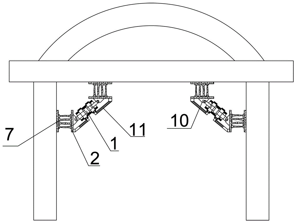
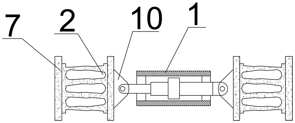
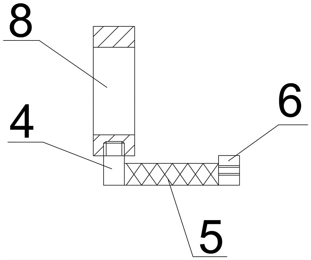
[0025] Such as Figure 1 ~ Figure 4 As shown, an intelligent temperature-controlled damper for a bridge includes a damper 1, the left and right ends of the damper 1 are respectively connected to the force component device 2 through the connecting seat 10, and the force component device 2 includes mild steel 9 and two fixing seats 3. At least two or more layers of mild steel 9 are arranged sequentially from top to bottom between the fixed seats 3, and each layer of mild steel 9 is connected in two corresponding mirror images. High parabola, the angle of the parabola is 110°, the side end surface of the mild steel 9 is parabolic, the mild steel 9 in odd numbers is a parabola with narrow left and wide right, and the mild steel 9 with even numbers is a parabola with wide left and narrow right The direction of the odd-numbered mild steel 9 is opposite to...


PUM

PropertyMeasurementUnit
phase transition temperatureaaaaaaaaaa

Abstract

The invention relates to an intelligent temperature-control damper used for a bridge. The left end and the right end of the damper are connected with force distribution devices through connecting seats correspondingly. Each force distribution device comprises soft steel and two fixing seats, and at least two layers of soft steel are sequentially arranged between the fixing seats from top to bottom. Each layer of soft steel comprises two pieces of soft steel which are correspondingly connected in a mirror image mode. The side end face of each piece of soft steel is in a parabola shape. Each connecting seat is fixed to the corresponding fixing seat which is located on the same side of the corresponding force distribution device. A coating layer is smeared on the surface of each force distribution device. The connecting seat on the left side is hinged to one end of the damper. The connecting seat on the right side is fixedly connected with the other end of the damper. The outer walls on the two sides of the damper are each sleeved with a protection reinforcing device. The other end of each protection reinforcing device is fixed to the fixing seat of the corresponding force distribution device. By the adoption of the intelligent temperature-control damper, the service life of the damper is prolonged, the deformation resistance and the bearing capacity are high, and the problems that according to an existing damper, cracks happen to a concrete bridge due to temperature stress, and damping shock absorption is influenced by the temperature are solved.

Description

technical field [0001] The invention relates to the field of construction engineering, in particular to an intelligent temperature-controlled damper for bridges. Background technique [0002] In the 1930s, prestressed concrete and high-strength steel appeared one after another, and major progress was made in the research of material plasticity theory and limit theory, bridge vibration research, aerodynamic research, and soil mechanics research; thus, saving Bridge construction materials, reducing bridge weight, predicting foundation sinking depth and determining its bearing capacity provide a scientific basis; modern bridges mostly use prestressed reinforced concrete bridges, reinforced concrete bridges and steel bridges. [0003] The frequent occurrence of bridge accidents across the country will cause huge economic losses and negative social impact. [0004] In recent years, after the earthquake, bridges, as an important part of the "lifeline project", provide important s...

Claims


Application Information

Patent Timeline
Patent Type & Authority Patents(China)
IPC IPC(8): E01D19/04E01D19/00C09D125/14C09D7/12C09D5/33
CPCC08K3/22C08K3/24C08K7/20C09D5/004C09D7/61C09D7/70C09D125/14E01D19/00E01D19/04
Inventor 何伟
Owner NORTH CHINA UNIV OF WATER RESOURCES & ELECTRIC POWER
Learn More