Double pile casing construction method for controlling perpendicularity

A construction method and double-shroud technology, which are applied in basic structure engineering, construction, sheet pile walls, etc., can solve the problems of difficulty in running and vertical deviation of running, so as to reduce construction cost, reduce frictional resistance, and facilitate entry. sinking effect

Active Publication Date: 2016-06-15
SHENZHEN GONGKAN GEOTECHN GRP
5 Cites 9 Cited by

AI-Extracted Technical Summary

Problems solved by technology

[0004] The purpose of the present invention is to provide a double casing construction method for controlling the verticality, aiming at solvi...

Method used

1), positioning is accurate; Adopting the outside is the structure that outer casing 12 is in conjunction with interior casing 11, before construction, first puts down outer casing 12, then according to the lower actual position of outer casing 12, utilizes four locating points, accurately locate the center point of the pile hole, and then use the four positioning plates 13 on the inner wall of the outer casing 12 to locate the position of the inner casing 11, so that the center point of the inner casing of the inner casing 11 coincides with the center point of the pile hole, realizing Accurate positioning of the inner casing 11;
2), inner casing 11 sinks easily, verticality control is convenient; The sinking of outer casing 12 makes the frictional resistance when inner casing 11 is lowered into, and is more convenient for the sinking of inner casing 11 , can also be positioned better and more accurately, and can also control the verticality of the inner casing 11 relatively easily at the same time.
In the construction method provided above, outer casing 12 is as auxiliary casing, and it sinks as the positioning effect of inner casing 11; Inner casing 11 plays the effect of blocking weak fo...

Abstract

The invention relates to the technical field of cast-in-place pile construction and discloses a double pile casing construction method for controlling the perpendicularity. The double pile casing construction method comprises the following construction steps of (1) measuring and locating a pile position on situ, and arranging four crossed locating points; (2) vertically submerging an outer pile casing within an encirclement ring formed by the four locating points; and (3) respectively convexly arranging a locating plate on a position, aligning to each locating point, on the inner wall of the outer pile casing; and vertically submerging an inner pile casing in the outer pile casing, and respectively enabling the outer ends of the four locating plates to support against the outer surface of the inner pile casing. The outer pile casing and the inner pile casing simultaneously act, so that the frictional resistances of the outer pile casing and the inner pile casing in the submerging and withdrawing processes are reduced; the inner pile casing and the outer pile casing can be utilized repeatedly, so that the construction cost is reduced; the inner pile casing is limited and located by using the four locating plates to ensure that the central point of the inner pile casing is coincided with the central point of a pile hole, so that the inner pile casing is accurately located, and the pile forming quality is effectively ensured.

Application Domain

Technology Topic

Frictional resistanceBuilding construction

Image

  • Double pile casing construction method for controlling perpendicularity
  • Double pile casing construction method for controlling perpendicularity
  • Double pile casing construction method for controlling perpendicularity

Examples

  • Experimental program(1)

Example Embodiment

[0022] In order to make the objectives, technical solutions, and advantages of the present invention clearer, the following further describes the present invention in detail with reference to the accompanying drawings and embodiments. It should be understood that the specific embodiments described here are only used to explain the present invention, but not to limit the present invention.
[0023] The implementation of the present invention will be described in detail below in conjunction with specific embodiments.
[0024] Reference Figure 1 ~ Figure 3 Shown is a preferred embodiment provided by the present invention.
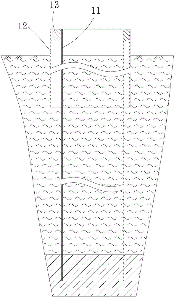
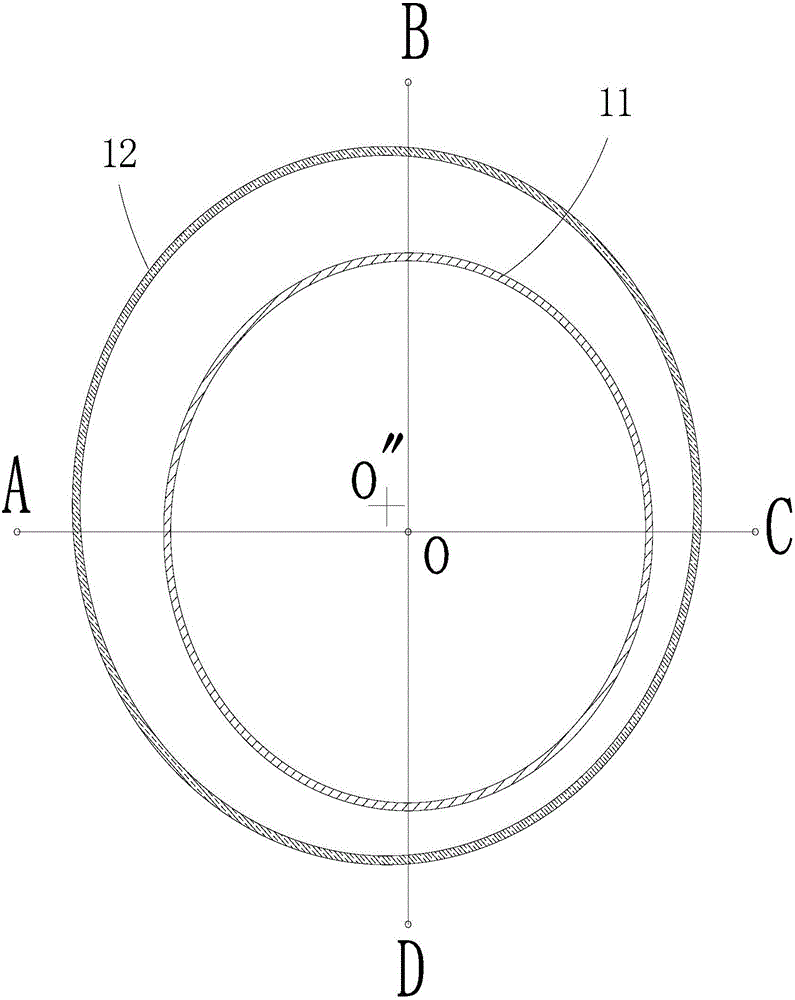
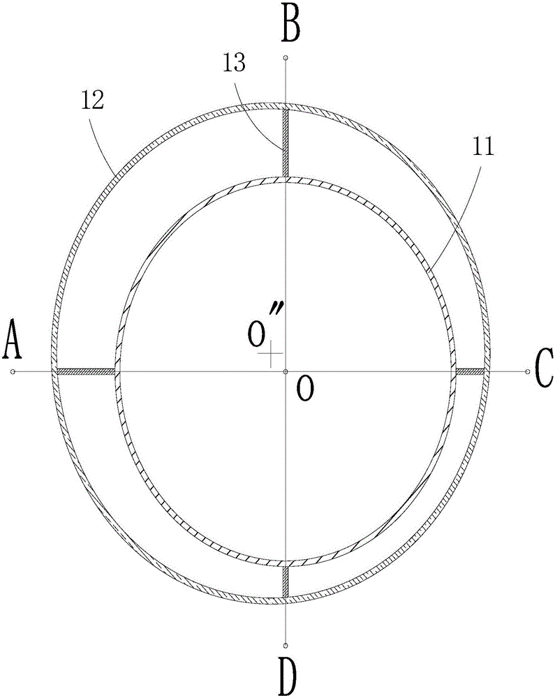
[0025] The construction method of the double protective tube for controlling verticality provided by the present invention can be used for sinking the deep long protective tube, so that the deep long protective tube has low friction and no deviation during the sinking process.
[0026] The construction method of double protective tube for controlling verticality includes the following construction steps:
[0027] 1). Perform pile position measurement and positioning on site, and set four cross-arranged positioning points. The center point of the cross of the four positioning points is the center point of the pile position, such as figure 2 and image 3 As shown in the figure, the four positioning points are A, B, C, and D respectively. Among them, the AC line and the BD line cross each other. The center point of the intersection between the two lines is O, which is the pile position. Center point
[0028] 2) The outer protective tube 12 is vertically lowered into the enclosure of the above four positioning points;
[0029] 3). Positioning plates 13 are respectively projected at the positions where the inner wall of the outer protective tube 12 is aligned with the positioning points. In this way, four positioning plates 13 are formed correspondingly, and the inner end of the positioning plate 13 is connected to the inner wall of the outer protective tube 12 , The outer end extends radially inward along the outer protective tube 12; the inner protective tube 11 is vertically sunk in the outer protective tube 12, keeping the center point of the inner protective tube 11 coincident with the center point of the pile position, and four positioning The outer ends of the plate 13 abut on the outer surface of the inner sheath 11 respectively.
[0030] In the construction method provided above, the outer protective tube 12 is used as an auxiliary protective tube, which serves as a positioning function for the sinking of the inner protective tube 11; the inner protective tube 11 plays a role of blocking weak formations and sandy soil layers and other unfavorable formations, avoiding later injection During pile construction, collapsed holes, shrinkage, and pile foundation displacement occurred. The outer protective tube 12 and the inner protective tube 11 act at the same time, which can effectively reduce the frictional resistance of the outer protective tube 12 and the inner protective tube 11 during the lowering and retracting process, so that the inner protective tube 11 and the outer protective tube 12 can be used multiple times. The construction cost is greatly reduced.
[0031] The double-barrel construction method for controlling verticality also has the following advantages:
[0032] 1) Accurate positioning; adopt the structure of the outer protective tube 12 on the outside and the inner protective tube 11 inside. Before construction, the outer protective tube 12 should be put down, and then according to the actual position of the outer protective tube 12, four positioning points are used , Accurately locate the center point of the pile hole, and then use the four positioning plates 13 on the inner wall of the outer sleeve 12 to locate the position of the inner sleeve 11, so that the center point of the inner sleeve 11 of the inner sleeve 11 coincides with the center point of the pile hole to achieve internal protection Accurate positioning of the barrel 11;
[0033] 2) The inner protective tube 11 is easy to sink, and the verticality control is convenient; the sinking of the outer protective tube 12 makes the frictional resistance of the inner protective tube 11 smaller when it is lowered, which is more convenient for the sinking of the inner protective tube 11, and can also Better accurate positioning and easier control of the verticality of the inner protective tube 11 at the same time.
[0034] 3) Effectively ensure the quality of piles; the combination of the inner protective tube 11 and the outer protective tube 12 can effectively ensure the verticality of the inner protective tube 11, thereby ensuring the verticality of the pile body and ensuring the quality of the pile.
[0035] In this embodiment, the outer protective tube 12 is a short protective tube, and the inner protective tube 11 is a long protective tube, that is, the length of the inner protective tube 11 is greater than the length of the outer protective tube 12. In general, the outer protective tube 12 The length is not more than one third of the length of the inner sheath 11.
[0036] In addition, the inner warp of the outer sheath 12 is greater than the inner diameter of the inner sheath 11 by more than 20 cm. Of course, as long as the inner diameter of the outer sheath 12 is larger than the diameter of the inner sheath 11 according to actual needs.
[0037] In the above step 2), the center point of the outer protective tube of the outer protective tube 12 after sinking (such as figure 2 and image 3 There is a deviation between the o") and the center point of the pile hole, allowing some deviation to a certain extent.
[0038] In step 2), a vibrating hammer is used to sink the outer protective tube 12, and the upper end of the sunken outer protective tube 12 extends outside the ground, and the height of the raised part is not less than about 30 cm.
[0039] After the sinking of the outer protective tube 12 is completed, a rotary drilling rig is used to dig out part of the soil in the protective tube 12. Generally, the 1.5m high soil in the protective tube 12 can be removed.
[0040] In this embodiment, the positioning plate 13 is flat, which facilitates the shaping of the positioning plate 13 and facilitates the positioning of the positioning plate 13 on the inner protective cylinder 11. In addition, the positioning plate 13 is arranged to extend along the radial direction of the outer sheath 12.
[0041] The above descriptions are only preferred embodiments of the present invention and are not intended to limit the present invention. Any modification, equivalent replacement and improvement made within the spirit and principle of the present invention shall be included in the protection of the present invention. Within range.

PUM

no PUM

Description & Claims & Application Information

We can also present the details of the Description, Claims and Application information to help users get a comprehensive understanding of the technical details of the patent, such as background art, summary of invention, brief description of drawings, description of embodiments, and other original content. On the other hand, users can also determine the specific scope of protection of the technology through the list of claims; as well as understand the changes in the life cycle of the technology with the presentation of the patent timeline. Login to view more.

Similar technology patents

Air-floated high-speed motorized spindle

InactiveCN102489726AEliminate mechanical frictionReduce frictionMachine tool componentsLarge fixed membersStatorEngineering
Owner:GUANGZHOU HAOZHI ELECTROMECHANICAL

Classification and recommendation of technical efficacy words

  • Reduce construction costs
  • Reduce friction

Friction reducing composition and method

Owner:LUBRIZOL OILFIELD SOLUTIONS

Carrier with integrated ducting

ActiveUS20120110909A1Reduce frictionLimiting bindingAir-treating devicesVehicle sub-unit featuresAirflowWindow shutter
Owner:MAGNA INTERNATIONAL INC
Why Eureka
Try Eureka