Geothermal wellhead power station system based on ORC systems and power generation method of geothermal wellhead power station system
A geothermal and power station technology, applied in the field of geothermal wellhead power station systems based on ORC systems, can solve the problems of inability to fully utilize heat energy in different levels, low energy utilization rate, and single utilization method, so as to achieve high heat energy utilization efficiency, improve utilization efficiency, and facilitate The effect of installation
- Summary
- Abstract
- Description
- Claims
- Application Information
AI Technical Summary
Problems solved by technology
Method used
Image
Examples
Embodiment 1
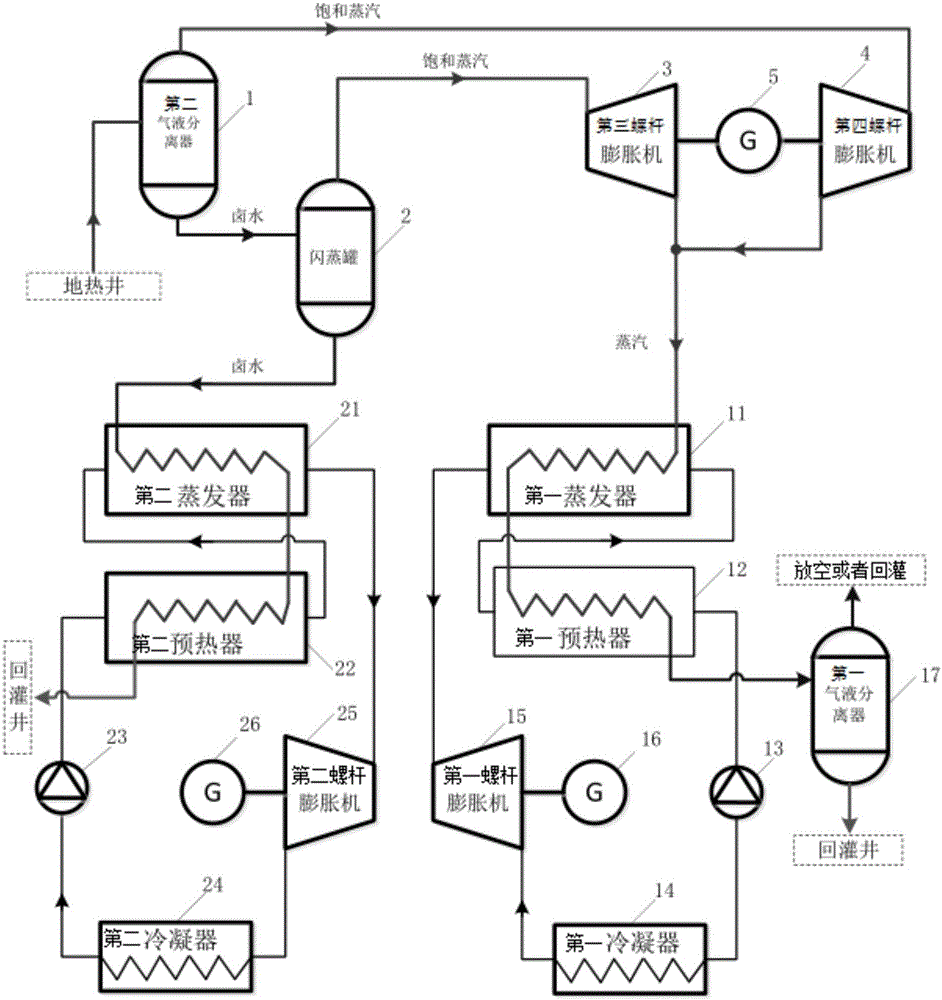
[0030] see figure 1 , the present invention discloses a geothermal wellhead power station system based on an ORC system. The geothermal wellhead power station system includes: a second gas-liquid separator 1, a flash tank 2, a third screw expander 3, and a fourth screw expander 4 , a third generator, a fourth generator, a first ORC system, and a second ORC system; the third generator and the fourth generator may be the same dual-shaft generator 5 .
[0031] The first end of the second gas-liquid separator 1 is connected to the third screw expander 3, and the saturated steam enters the third screw expander 3; the third screw expander 3 is connected to the double output shaft generator 5, and the third screw expander 3 Connect to the first ORC system.
[0032] The second end of the second gas-liquid separator 1 is connected to the flash tank 2, and the flash tank is connected to the fourth screw expander 4. The high-temperature and high-pressure brine enters the flash tank 2, a...
Embodiment 2
[0042] The difference between this embodiment and Embodiment 1 is that in this embodiment, the working medium delivery mechanism (the first working medium delivery mechanism and the second working medium delivery mechanism) is a combined working medium pump, and the combined working medium pump includes at least one A variable frequency pump and at least one fixed frequency pump, each variable frequency pump and fixed frequency pump are connected in parallel.
[0043] In the heat engine stage, start-up stage and partial load conditions, only use variable frequency pumps, or use a combination of part or all variable frequency pumps and part or all fixed frequency pumps; in full load conditions, use variable frequency pumps and fixed frequency pumps The pumps are all on.
[0044] At the same time, the system also includes a second working condition automatic identification module, a second demand calculation module, and a second switching module.
[0045] The second working con...
Embodiment 3
[0050] The difference between this embodiment and Embodiment 1 is that in this embodiment, the condenser (first condenser, second condenser) is a combined condenser, and the combined condenser includes at least one air-cooled condenser and at least one evaporative condenser. Condenser, each air-cooled condenser and evaporative condenser are connected in parallel.
[0051] When the ambient temperature is higher than the first set temperature, the evaporative condenser plays a major role in reducing the condensation temperature of the system. When the ambient temperature is lower than the second set temperature, the air-cooled condenser plays a major role in reducing the condensation temperature of the system.
[0052] In addition, the system further includes a second working condition automatic identification module, a second demand calculation module, and a second switching module.
[0053] The second working condition automatic identification module is used to identify the w...
PUM
 Abstract
Description
Claims
Application Information
 - R&D
- Intellectual Property
- Life Sciences
- Materials
- Tech Scout
- Unparalleled Data Quality
- Higher Quality Content
- 60% Fewer Hallucinations
Browse by: Latest US Patents, China's latest patents, Technical Efficacy Thesaurus, Application Domain, Technology Topic, Popular Technical Reports.
© 2025 PatSnap. All rights reserved.Legal|Privacy policy|Modern Slavery Act Transparency Statement|Sitemap|About US| Contact US: help@patsnap.com

