Universal-type flow meter based on wing principle

A general-purpose flowmeter technology, applied in the direction of volume/mass flow generated by mechanical effects, fluid flow detected by measuring pressure difference, etc., can solve problems such as large limitations of process pipelines, easy blockage of pressure guiding pipes, and inconvenient maintenance , to achieve the effect of good sensing repeatability, high reliability and convenient maintenance

Inactive Publication Date: 2016-06-15
FUJIAN YUNCHUANG INTEGRATED TECH SERVICES
View PDF9 Cites 1 Cited by
  • Summary
  • Abstract
  • Description
  • Claims
  • Application Information

AI Technical Summary

Problems solved by technology

[0008] C. Since the relative flow velocity of the fluid and the "wing" is far lower than the relative velocity of the wing and the air in the flight of the aircraft when the wing-shaped throttle is used for measurement, so if the sensitivity is to be improved, the "machine" must be increased. Wing", but this will increase the pressure loss of the air duct, which will increase the energy consumption of the process and increase the manufacturing cost
[0009] D. In order to improve the accuracy during measurement, multi-point sampling is required to take the average value, the structure is relatively complex, there are many links, and the reliability is not high enough
[0010] To sum up, the flow measurement device based on the principle of airfoil in the prior art, the pressure guiding pipe is easy to block, the scope of use and the layout of the process pipeline are very limited, the volume is large, the energy consumption is large, the structure is relatively complicated, and the maintenance is not enough Convenience, high cost, low reliability, unsatisfactory use effect

Method used


Image

  • Universal-type flow meter based on wing principle
  • Universal-type flow meter based on wing principle
  • Universal-type flow meter based on wing principle

Examples


Embodiment Construction

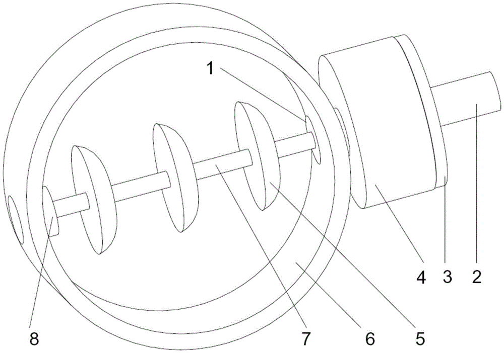
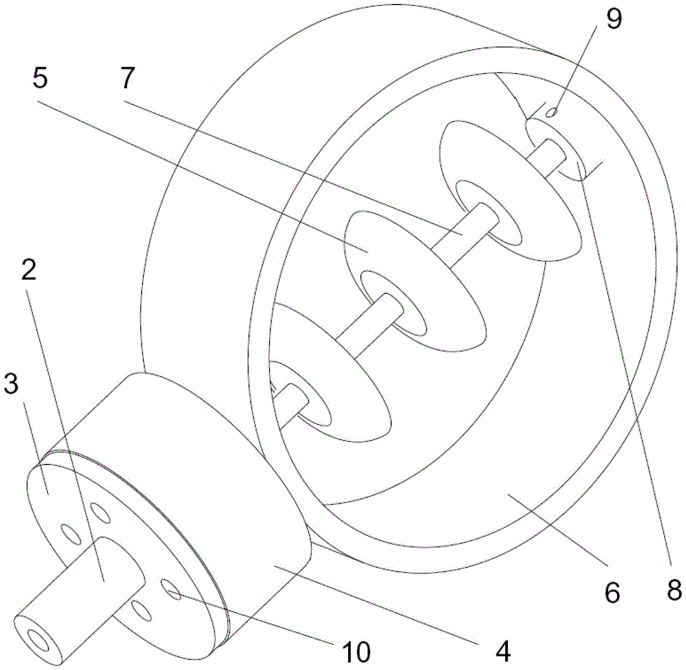
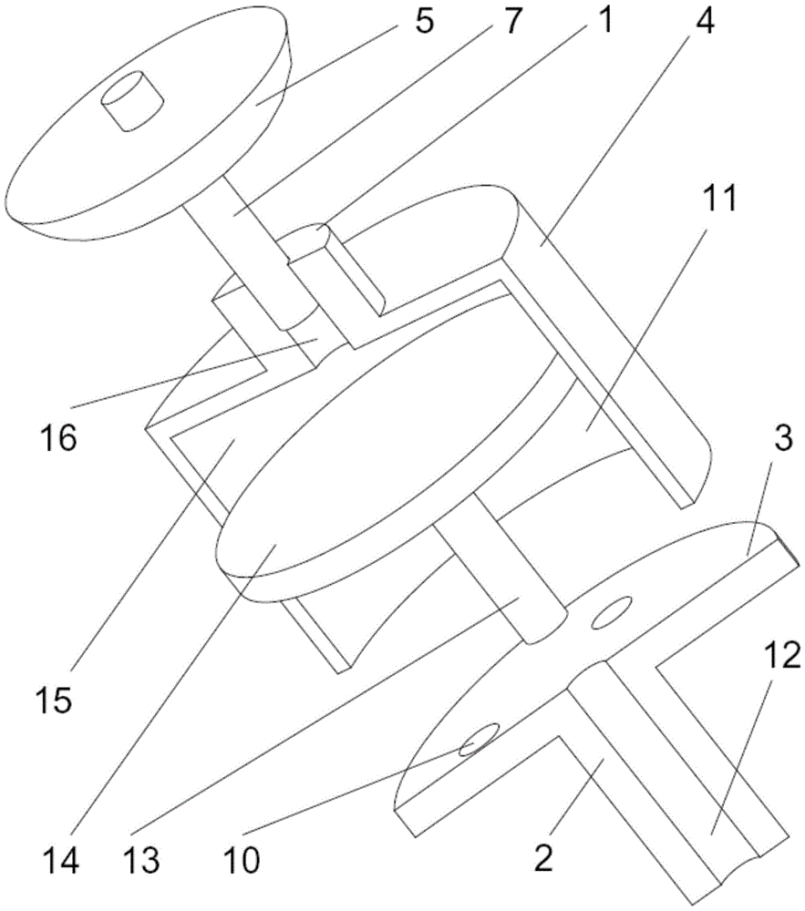
[0032] Embodiments of the present invention, such as Figure 1 to Figure 6As shown, the general-purpose flowmeter based on the wing principle includes a wing-type sensor set in the process pipeline 6, and a detection signal transmission device adapted to connect with the wing-type sensor; the wing The sensor includes a plurality of disk wings 5 ​​distributed at intervals and coaxially connected in series through a shared wing shaft 7 arranged horizontally. The axis of the shared wing shaft 7 is also perpendicular to the central axis of the process pipeline 6. The cross section of the wing 5 is in the shape of D; the inner wall surface of the tube on the side of the straight surface of the D is provided with a shaft sleeve 8, and the tube wall on the side of the curved surface of the D is provided with a supporting cylinder sleeve 1, and the supporting cylinder The outer end of the sleeve 1 protrudes from the wall of the process pipeline 6; the two ends of the common wing shaft...


PUM


Abstract

The invention discloses a general-purpose flowmeter based on the wing principle, which includes a wing-type sensing element arranged in a pipeline, and a detection signal transmission device connected with the sensing element; the sensing element includes a plurality of spaced distribution and The disc wings are coaxially connected in series through the shared wing shaft arranged horizontally. The wing axis is perpendicular to the pipe axis, and the cross section of the disc wing is D-shaped; The pipe wall on the side of the arc curved surface is provided with a supporting cylinder sleeve, and the outer end of the supporting cylinder sleeve protrudes from the pipe; the two ends of the shared wing shaft are respectively erected at two corresponding places on the pipe wall through the shaft sleeve and the supporting cylinder sleeve; The wing shaft is rotatable and can translate left and right; the detection signal transmission device is connected to the pressure transmitter through the end face of the common wing shaft on the side of the curved surface of the D word through a hydraulic jack type pressure amplifying device. High reliability and sensitivity, free pipeline layout, convenient maintenance, small pressure loss, simple structure, and can adapt to various fluid measurement.

Description

technical field [0001] The invention belongs to the technical field of metering and detection, and relates to flow metering technology, in particular to a general-purpose flowmeter based on the wing principle. Background technique [0002] Flow metering is the most commonly used measurement in thermal engineering. There are many methods of flow measurement. In the industrial field, the instruments for measuring fluid flow are collectively called flow meters or flow meters. It is one of the most important instruments in industrial measurement. With the development of industry, the accuracy and range of flow measurement are required to be higher and higher. In order to adapt to various purposes, various types of flowmeters have come out one after another, such as target flowmeter, positive displacement flowmeter, turbine flowmeter, differential flowmeter, etc. Pressure flowmeter, variable area flowmeter, electromagnetic flowmeter, ultrasonic flowmeter, vortex flowmeter, etc....

Claims


Application Information

Patent Timeline
IPC IPC(8): G01F1/36G01F1/40
CPCG01F1/36G01F1/40
Inventor 陈应明
Owner FUJIAN YUNCHUANG INTEGRATED TECH SERVICES
Why Eureka
Try Eureka