
Noise testing device and testing method for automobile exhaust tail pipe

A technology for noise testing and automobile exhaust, applied to measuring devices, measuring ultrasonic/sonic/infrasonic waves, instruments, etc., can solve problems such as inaccurate data, different exhaust noise, and suction cup falling off, so as to improve accuracy and practicability Strong, accurate results

Active Publication Date: 2016-06-15
HANGZHOU BRANCH ZHEJIANG GEELY AUTOMOBILE RES INST +2
View PDF8 Cites 2 Cited by
  • Summary
  • Abstract
  • Description
  • Claims
  • Application Information

AI Technical Summary

Problems solved by technology

But these two kinds of devices have the following defects at least: (1) because these two devices are all to be adsorbed on the bumper by the suction cup, the position of the microphone and the exhaust tailpipe cannot be kept fixed due to the vibration of the vehicle running; The exhaust noise at different distances from the tailpipe is different, which will affect the accuracy of the test to a certain extent
And when testing harsh working conditions such as acceleration, the suction cup will fall off the bumper, making it impossible to complete the test
(2) The influence of temperature factors on test results is not considered
Due to the high exhaust temperature of the exhaust tailpipe, it will have a great impact on the performance of the noise measuring instrument
The inventor found that when the operating temperature of the acoustic sensor exceeds 80°C, the test data is inaccurate
The inaccuracy of the test will directly affect the evaluation or improvement based on the test results
(3) The position adjustment of the microphone is not flexible enough, and only one microphone is set, and only one set of data can be tested for each test. If test data at different positions are needed, the test can only be done again, or multiple tests can be installed in one test. test device, very inconvenient

Method used


Image

  • Noise testing device and testing method for automobile exhaust tail pipe
  • Noise testing device and testing method for automobile exhaust tail pipe
  • Noise testing device and testing method for automobile exhaust tail pipe

Examples


Embodiment Construction

[0027] The content of the present invention will be described in detail below in conjunction with the accompanying drawings and embodiments.

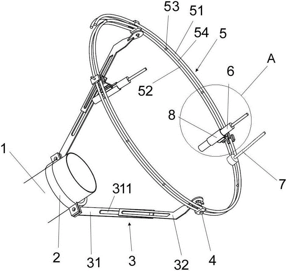
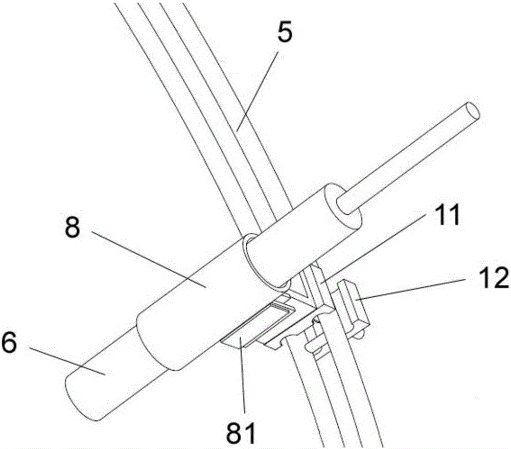
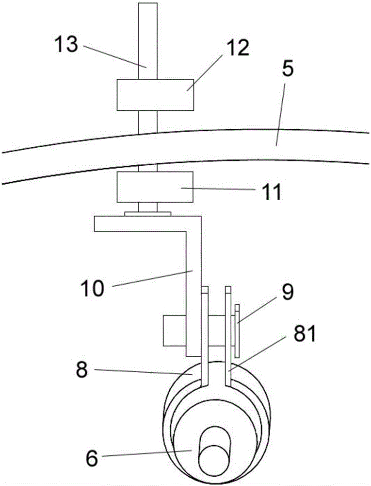
[0028] Such as figure 1 As shown, the automobile exhaust tailpipe noise testing device of the present invention includes an acoustic sensor 6 for collecting the noise data of the exhaust tailpipe and a data processor (not shown) for processing the noise data, and adjacent The acoustic sensor 6 is provided with a temperature sensor 7 . The temperature sensor 7 is used to collect temperature data at the location where the acoustic sensor 6 is located. The collected temperature data and noise data are sent to the data processor, and the data processor judges the validity of the noise data according to the temperature data and performs certain processing on the effective noise data.

[0029] The automobile exhaust tailpipe noise testing device of the present invention also includes a fixing frame 2 and a ring support 5 . The fixing brack...


PUM


Abstract

The invention discloses a noise testing device and a testing method for an automobile exhaust tail pipe. The noise testing device for the automobile exhaust tail pipe comprises an acoustic sensor for collecting noise data of the exhaust tail pipe, a data processor for processing the noise data and a temperature sensor arranged near the acoustic sensor and used for collecting temperature data of the position of the acoustic sensor. When a noise test is performed, the temperature can simultaneously monitor temperature condition of the acoustic sensor in real time. The noise testing device for the automobile exhaust tail pipe arranged on the exhaust tail pipe is more fixed and reliable than using an adhesive disc to adhere the device to a bumper, the acoustic sensor is unchanged relative to the position of an exhaust tail pipe port, and the above is beneficial to improve the accuracy of the test. The device and the method are further suitable for testing a bad condition of speed up driving. The distance and the angle between the acoustic sensor and the exhaust tail pipe port can also be conveniently adjusted.

Description

[0001] This application is a divisional application of the invention patent application with the filing date of September 6, 2012, the application number of 201210326528.9, and the title of "automobile exhaust tailpipe noise testing device and testing method". technical field [0002] The invention relates to noise testing technology, more specifically, to a noise testing device and a testing method of an automobile exhaust tailpipe. Background technique [0003] At present, automobile noise is one of the main pollution sources of urban environmental noise. Among the many noise sources of automobiles, exhaust noise accounts for a large proportion. The test of automobile exhaust noise provides important data reference for the NVH (Noise, Vibration, Harshness) quality design of vehicles. NVH is one of the concerns of major vehicle manufacturers and parts companies in the international automotive industry. According to statistics, about 1 / 3 of the failure problems of the whol...

Claims


Application Information

Patent Timeline
Patent Type & Authority Applications(China)
IPC IPC(8): G01H17/00
CPCG01H17/00
Inventor 宋百忠王海林刘强杨安志赵福全
Owner HANGZHOU BRANCH ZHEJIANG GEELY AUTOMOBILE RES INST
Learn More