Fault monitoring system for power transmission line

A transmission line and fault monitoring technology, applied in the field of power system, can solve the problems of delayed positioning time, high degree of automation incompatibility, etc., and achieve the effect of quickly eliminating faults

Inactive Publication Date: 2016-06-15
ZHANGQIU POWER SUPPLY CO OF STATE GRID SHANDONG ELECTRIC POWER CO
View PDF3 Cites 25 Cited by
  • Summary
  • Abstract
  • Description
  • Claims
  • Application Information

AI Technical Summary

Problems solved by technology

Unnecessary power supply interruption for users of non-faulty lines due to line selection
Visual line inspection and positioning consume a lot of manpower and material resources, delaying the positioning time
These two methods are extremely incompatible with the high degree of automation of the modern power grid

Method used


Image

  • Fault monitoring system for power transmission line
  • Fault monitoring system for power transmission line
  • Fault monitoring system for power transmission line

Examples


Embodiment Construction

[0053] In order to make the purpose, features and advantages of the present invention more obvious and understandable, the technical solutions protected by the present invention will be clearly and completely described below using specific embodiments and accompanying drawings. Obviously, the implementation described below Examples are only some embodiments of the present invention, but not all embodiments. Based on the embodiments in this patent, all other embodiments obtained by persons of ordinary skill in the art without creative efforts fall within the protection scope of this patent.

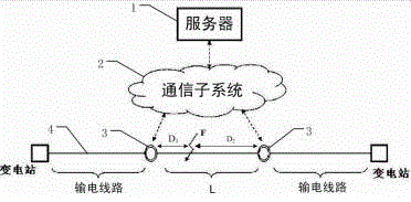
[0054] This embodiment provides a transmission line fault monitoring system, such as figure 1 As shown, it includes: a terminal monitoring device 3, a communication subsystem 2 and a server 1 arranged on each section of the monitored transmission line 4;

[0055] The terminal monitoring device 3 includes: a measurement module, a terminal host, an energy supply module and an optical networ...


PUM


Abstract

The invention discloses a transmission line fault monitoring system, comprising: a terminal monitoring device, a communication subsystem and a server arranged on each section of the monitored transmission line; a measurement module is used to monitor the data information of the transmission line, and upload the collected data in real time To the server; the terminal host aggregates, preprocesses and uploads the monitored data and collected data, and controls the terminal monitoring device according to the command sent by the server; the camera device monitors visible light video image data, and the infrared thermal imager collects infrared image data ; The camera device and the infrared thermal imager are set in the same airborne platform to ensure the correspondence between the infrared image data and the monitoring object; the microwave Doppler detector detects foreign matter intrusion into the transmission line; Surveillance, analysis and early warning requirements. Dividing the transmission line into several sections can construct accurate transmission line fault location, so as to realize rapid fault removal.

Description

technical field [0001] The invention relates to the field of power systems, in particular to a transmission line fault monitoring system. Background technique [0002] During the operation of the power system, failures often occur. The unplanned power supply interruption caused by the failure will stop production, cause chaos in life, and even endanger the safety of people and equipment, resulting in very serious consequences. The statistics of the power system show that most of the faults in the distribution network operation are short-circuit faults, and more than 90% of them are single-phase ground faults. The main cause of short circuit is that the phase-to-phase insulation or phase-to-ground insulation of the current-carrying part of the electrical equipment is damaged. Therefore, after a single-phase ground fault occurs in the distribution network, if fast and accurate positioning can be achieved, not only can the line be repaired as soon as possible to ensure the rel...

Claims


Application Information

Patent Timeline
Patent Type & Authority Applications(China)
IPC IPC(8): G01R31/08
CPCG01R31/085
Inventor 许大力苏玉磊刘广军李振吉齐光利王永进高兆军李庆江张伟马玉杰刘振华李岩刘秋霞李毅赵利强孟刚
Owner ZHANGQIU POWER SUPPLY CO OF STATE GRID SHANDONG ELECTRIC POWER CO
Why Eureka
Try Eureka