Multi-frequency signal generation method based on DDS chip

A DDS chip and multi-frequency signal technology, applied in radio wave measurement systems, instruments, etc., can solve problems such as complex circuits and large frequency deviations, and achieve the effect of hardware logic occupying less resources and simple and effective implementation methods

Inactive Publication Date: 2016-06-15
LEIHUA ELECTRONICS TECH RES INST AVIATION IND OF CHINA
View PDF4 Cites 0 Cited by
  • Summary
  • Abstract
  • Description
  • Claims
  • Application Information

AI Technical Summary

Problems solved by technology

The advantage of this method is that it can generate a large frequency offset. The disadvantage is that it needs to use the PLL circuit to lock the frequency, and the circuit is more complicated.

Method used


Image

  • Multi-frequency signal generation method based on DDS chip
  • Multi-frequency signal generation method based on DDS chip
  • Multi-frequency signal generation method based on DDS chip

Examples


Embodiment

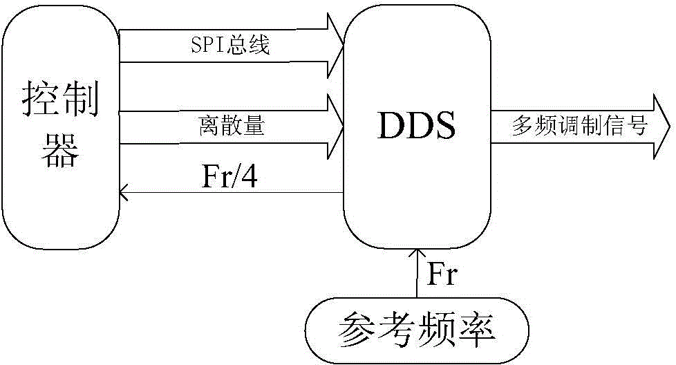
[0033] This patent selects the JDDS9910 of CLP 58, which is a direct digital frequency synthesizer with a built-in 14-bit DAC, supports a sampling rate up to 1GHz, integrates a static RAM inside, and supports a combination of frequency, phase or amplitude modulation. It is composed of 1024*32bits control words, which can be divided into 8 independent spaces and configured separately; the controller can be selected from various FPGAs, and an FPGA of Spartan3 from Xilinx Company is selected in this patent, and it has configurable IOs up to 144 One is the preferred chip with low cost and high performance. It has rich and flexible configurable logic resources. It can also use the attached PLL soft core to synthesize various clocks you want. The FPGA needs to complete the initialization of the DDS chip, including DDS Initial configuration, RAM working mode configuration, and phase waveform data are written into DDS RAM. Use JDDS9910 to generate multi-frequency signals whose center ...


PUM


Abstract

The invention belongs to the technical field of radar signal generation, in particular to a multi-frequency signal generation method. The invention utilizes the DDS chip, supplemented by FPGA control, uses tools such as matlab to calculate the phase waveform data in a cycle, and writes the data into the DDS chip RAM through hardware logic. The curve and the preset playback rate will play the signal to complete the multi-frequency signal modulation.

Description

technical field [0001] The invention belongs to the technical field of radar signal generation, in particular to a multi-frequency signal generation method. Background technique [0002] The multi-frequency signal refers to the multi-carrier frequency signal transmitted at the same time, and each frequency point signal is still a single-frequency signal without modulation. Multi-frequency signals can cause frequency measurement errors and sorting difficulties in electronic reconnaissance equipment, and also force electronic interference equipment to widen the bandwidth of interference signals, thereby reducing the interference effect. During radar receiving and processing, only one of the carrier frequency signals is received and processed, which is still narrow-band receiving and processing. If the multi-frequency signal is generated by simple addition of single-frequency signals, as the number of channels increases, the noise will increase rapidly after the signal passes ...

Claims


Application Information

Patent Timeline
Patent Type & Authority Applications(China)
IPC IPC(8): G01S7/35
Inventor 包可佳苏光锋唐琦
Owner LEIHUA ELECTRONICS TECH RES INST AVIATION IND OF CHINA
Why Eureka
Try Eureka