Helicopter-borne laser radar platform three-dimensional attitude angle complex vibration real-time compensation method and device

A technology of three-dimensional attitude and laser radar, which is applied in the direction of radio wave measurement system, instrument, etc., can solve the problem that the three-axis attitude angle vibration cannot be compensated at the same time

Active Publication Date: 2016-06-15
SHANDONG UNIV OF TECH
View PDF7 Cites 24 Cited by
  • Summary
  • Abstract
  • Description
  • Claims
  • Application Information

AI Technical Summary

Problems solved by technology

[0005] Among the existing real-time compensation methods for the airborne lidar payload platform, such as in patent ZL201010183492.4, it proposes a real-time compensation method for the pitch angle change of the airborne lidar payload platform, and in patent ZL201010180527.9 In it, it proposes a real-time compensation method for the roll angle change of the airborne lidar payload platform. Compensation of the attitude angle on the ground, but it is impossible to realize the simultaneous compensation of the vibration of the three-axis attitude angle

Method used


Image

  • Helicopter-borne laser radar platform three-dimensional attitude angle complex vibration real-time compensation method and device
  • Helicopter-borne laser radar platform three-dimensional attitude angle complex vibration real-time compensation method and device
  • Helicopter-borne laser radar platform three-dimensional attitude angle complex vibration real-time compensation method and device

Examples


Embodiment Construction

[0024] The embodiments of the patent of the present invention will be described in further detail below in conjunction with the accompanying drawings.

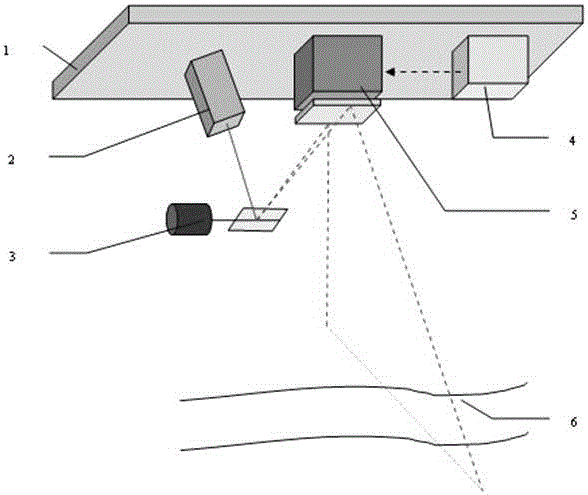
[0025] figure 1 It is the working principle diagram of conventional helicopter-borne lidar. The figure depicts the basic structure of a conventional airborne lidar system. Among them, (1) is a helicopter-borne platform, (2) is a high-frequency laser pulse rangefinder, (3) is a one-dimensional scanning swing galvanometer system, (4) ) Is a three-dimensional high-precision gyroscope. This is the helicopter-borne lidar system without attitude angle compensation. When the airborne platform is stable and there is no attitude angle vibration in the three-axis directions, the laser pulse beam emitted by the laser will be reflected by the one-dimensional scanning swing galvanometer system, and a scanning line will be generated perpendicular to the flight direction of the aircraft (assuming The measured ground is a horizontal plane), as...


PUM


Abstract

The invention relates to a helicopter-borne laser radar platform three-dimensional attitude angle complex vibration real-time compensation method and device. In a helicopter-borne laser radar system, the three-dimensional attitude angle vibration compensation device is additionally adopted, and the three-dimensional attitude angle vibration compensation is provided with a large-sized reflector. A magnetic universal bearing is adopted to support the large-sized reflector, so that the large-sized reflector can rotate around an x axis and a y axis simultaneously; rotation angle closed-loop control on the rotation of the large-sized reflector around the x axis and the y axis can be realized through adopting a direct-acting motor and a grating ruler displacement sensor, so that the coupling of the rotation of the large-sized reflector around the x axis and the y axis can be realized; and a direct-current torque motor and gear transmission mode is adopted to realize the rotation of the large-sized reflector around a z axis. With the three-dimensional attitude angle vibration compensation device adopted, a laser pulse beam which is deflected because of the influence of airborne platform three-dimensional attitude angle vibration can be corrected to an ideal scanning direction which is realized when airborne platform attitude angle vibration does not exist, and therefore, real-time complete compensation for the airborne platform three-dimensional attitude angle vibration can be realized, and adverse influence of the helicopter-borne platform three-dimensional attitude angle vibration on the measurement point cloud of a laser radar can be eliminated.

Description

Technical field [0001] The invention relates to the problem of real-time high-precision compensation for the adverse effects of complex vibration of a helicopter-borne platform on the three-dimensional imaging of an airborne lidar. Background technique [0002] Lidar has the advantages of high imaging accuracy, high operating efficiency, and long detection distance, while helicopters have the advantages of flexible flight, low requirements for take-off and landing locations, and low flight altitude, which is suitable for measurement of various complex terrains. Combining the two, helicopter-borne lidar has been widely used in many fields such as terrain surveying and mapping, urban modeling, and power line surveying. [0003] In the working process of airborne lidar, the movement of the airborne platform is required to be regular, and the helicopter is usually required to fly in a straight line at a uniform speed, so that the detection point cloud of the lidar can cover the area re...

Claims


Application Information

Patent Timeline
Patent Type & Authority Applications(China)
IPC IPC(8): G01S7/497
CPCG01S7/497Y02A90/10
Inventor 王建军苗松李云龙
Owner SHANDONG UNIV OF TECH
Why Eureka
Try Eureka