Large resection rate milling tremor monitoring method considering rigidity time-varying

A milling chatter and stiffness time-varying technology, applied in the field of machining, can solve the problems of increased chatter, errors, and poor dynamic characteristics of the tool-workpiece system.

Inactive Publication Date: 2016-06-15
TIANJIN UNIV OF TECH & EDUCATION TEACHER DEV CENT OF CHINA VOCATIONAL TRAINING & GUIDANCE
View PDF2 Cites 19 Cited by
  • Summary
  • Abstract
  • Description
  • Claims
  • Application Information

AI Technical Summary

Problems solved by technology

It should be noted that after milling to a thin wall with a large material removal rate, the stiffness of the workpiece shows a time-varying decrease trend, and the dynamic characteristics of the tool-workpiece system become worse and lead to aggravated chatter. The traditional milling chatter monitoring will have errors , especially for high-speed and removal rate up to 90% of the machining process, this error will not be negligible

Method used


Image

  • Large resection rate milling tremor monitoring method considering rigidity time-varying
  • Large resection rate milling tremor monitoring method considering rigidity time-varying
  • Large resection rate milling tremor monitoring method considering rigidity time-varying

Examples


Embodiment Construction

[0027] In order to make the object, technical solution and advantages of the present invention clearer, the present invention will be further described in detail below in conjunction with the accompanying drawings.

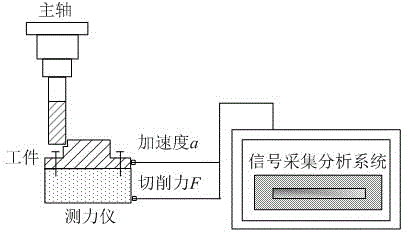
[0028] The tool-workpiece coupling system is simplified as a transfer function model with the cutting force as the excitation signal and the tool-workpiece coupling system as the frequency response object. The geometric relationship between the tool and workpiece displacement in the cutting process is established to carry out the transfer function coupling.

[0029] From the physical meaning of the transfer function, the transfer functions Hwx and Hwy in the x and y directions of the workpiece are expressed as

[0030] (4)

[0031] (5)

[0032] Among them, Re[Hwx], Re[Hwy] and Im[Hwx], Im[Hwy] are the real part and imaginary part of the workpiece transfer function matrix in the x and y directions, m / N; Xwx and Xwy are x and y The displacement of the workpiec...


PUM


Abstract

The invention relates to a large resection rate milling tremor monitoring method considering rigidity time-varying, and relates to the large resection rate high precision manufacture field with material resection rate above 80%; the monitoring method comprises the following steps: S10, cutter-workpiece coupling system time-varying transfer function modeling: substituting a relation between the transfer function and cutting force and displacement into a built displacement equation so as to obtain a cutter-workpiece coupling system time-varying transfer function model; S20, building a time-verying coupling transfer function online monitoring measuring system so as to monitor the transfer function in real time; S30, building a milling tremor stability kinetic model, substituting the transfer function value measured by the S20 into the kinetic model in the S30, monitoring tremor generation, and obtaining a non-tremor processing parameter scope; S40, providing a tremor optimization processing parameter control guide scheme according to the S30.

Description

technical field [0001] The invention belongs to the field of mechanical processing and relates to a chatter monitoring method, in particular to a chatter monitoring method for milling with a large cutting rate considering the time-varying stiffness. Background technique [0002] Machining chatter is an important factor affecting the accuracy of workpieces. Establishing a dynamic model of milling chatter stability is the first step in chatter monitoring. Stability dynamics modeling was first established by Tobias and Tlusty in the range of right-angle turning, and then researchers expanded the scope of application of the model, such as applications in milling and grinding. The dynamic model has experienced the development from single-degree-of-freedom modeling to multi-degree-of-freedom modeling, from low-speed machining to high-speed machining, modeling from time domain to frequency domain and time-frequency domain, and the dimension of cutting influencing factors from two-d...

Claims


Application Information

Patent Timeline
Patent Type & Authority Applications(China)
IPC IPC(8): G06F19/00B23Q17/12B23Q15/12
Inventor 蒋永翔马骏李秋朱娜张子淼
Owner TIANJIN UNIV OF TECH & EDUCATION TEACHER DEV CENT OF CHINA VOCATIONAL TRAINING & GUIDANCE
Why Eureka
Try Eureka