Reinforcement system for substation outlets

A technology for substations and wire jumpers, which is applied in the directions of busbar/line layout, cable space arrangement/configuration, etc. It can solve problems such as long length of down conductors, twisted and broken spacers, broken strands of down conductors, etc., to reduce lateral Effects of wind pressure, preventing strand breakage, and increasing weight

Active Publication Date: 2018-07-24
CHINA ENERGY ENG GRP GUANGDONG ELECTRIC POWER DESIGN INST CO LTD
View PDF5 Cites 0 Cited by
  • Summary
  • Abstract
  • Description
  • Claims
  • Application Information

AI Technical Summary

Problems solved by technology

[0002] At present, the outgoing wires of the substation are connected to the jumper wires in the series, and the outgoing wires are directly connected to the T-shaped clamps of the arrester terminals with down-conductors. It can work normally, but in the case of a strong typhoon, the down conductor swings repeatedly due to the strong wind, the length of the down conductor is long, and the end of the down conductor keeps bending under the strong wind, which may easily cause the down conductor to break Strands and spacers are twisted and broken, and most of the broken strands occur on the terminals of the arrester. The T-shaped clamp is installed on the terminal of the arrester. The edge of the clamp is sharp. Cutting the down conductor, resulting in broken strands of the down conductor

Method used


Image

  • Reinforcement system for substation outlets

Examples


Embodiment Construction

[0018] Embodiments of the present invention are described in detail below in conjunction with accompanying drawings:

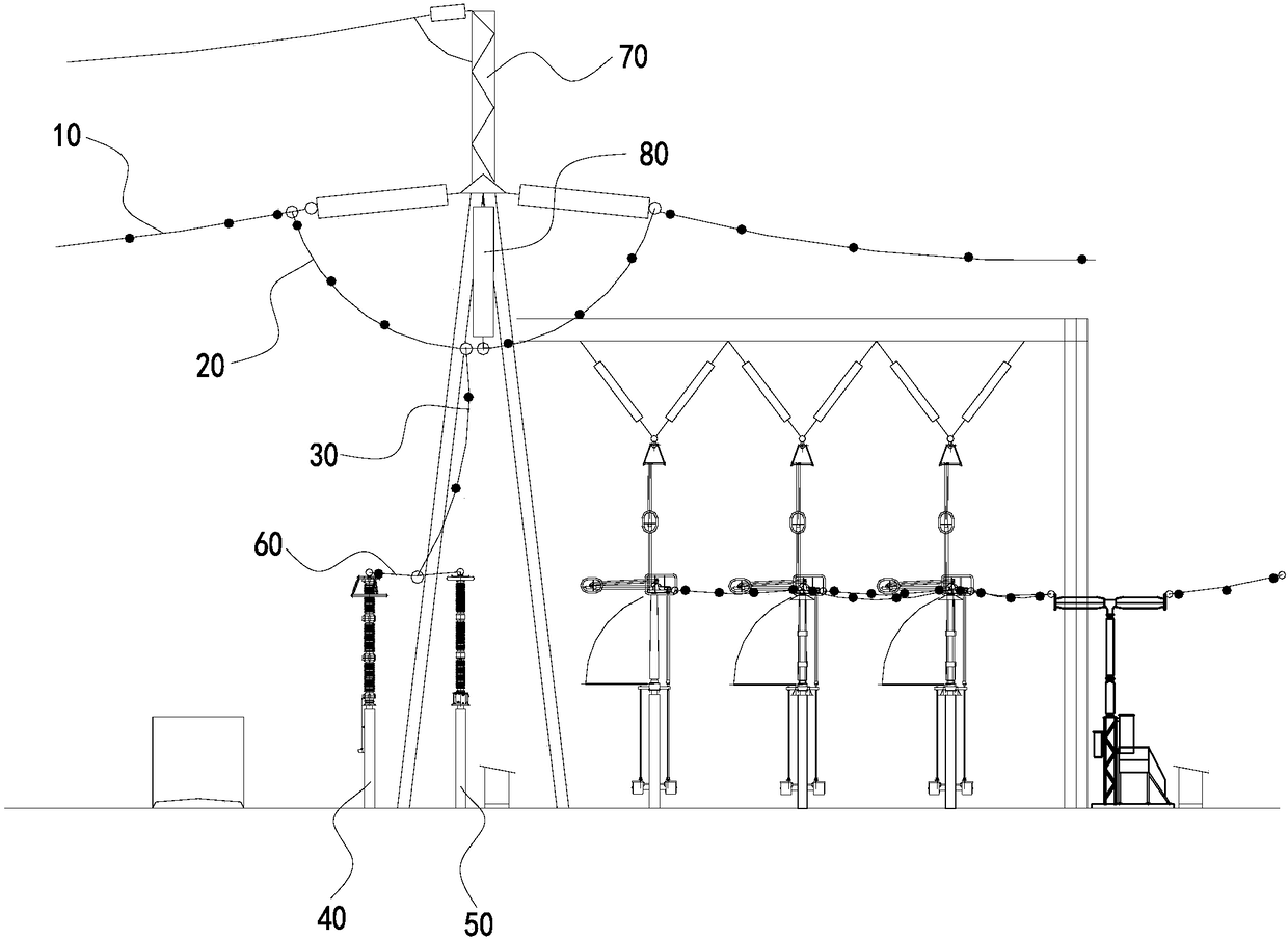
[0019] Such as figure 1 As shown, a substation outgoing line reinforcement system includes an outgoing wire 10, a jumper wire 20, a down conductor 30, a lightning arrester 40 and a voltage transformer 50 located below the outgoing wire 10, and the two ends are respectively connected to the lightning arrester 40 and the voltage transformer 50. The two ends of the jumper wire 20 are respectively connected to the outgoing wire 10, one end of the down conductor 30 is connected to the jumper wire 20, and the other end is connected to the connecting wire 60.

[0020] One end of the down conductor 30 is connected to the jumper wire 20, and the other end is connected to the connecting wire 60. Compared with the traditional wiring method, the length of the down conductor 30 is shortened, the lateral wind pressure of the down conductor 30 is reduced, and the jumper wire...


PUM


Abstract

The invention relates to a transformer substation outgoing line strengthening system. The transformer substation outgoing line strengthening system comprises an outgoing line wire, a jumper wire, a down lead, a lightning arrester, a voltage transformer and a connecting wire, wherein the lightning arrester and the voltage transformer are positioned below the outgoing line wire; two ends of the connecting wire are respectively connected with the lightning arrester and the voltage transformer; two ends of the jumper wire are respectively connected with the outgoing line wire; one end of the down lead is connected with the jumper wire, and the other end of the down lead is connected to the connecting wire. Due to the fact that one end of the down lead is connected with the jumper wire and the other end of the down lead is connected to the connecting wire, compared with a traditional wire connecting manner, the length of the down lead is shortened, the lateral wind pressure of the down lead is reduced, the jumper wire and the down lead are connected together as a whole body, the weight in the air is increased, and the swing amplitude of the down lead in the wind is further reduced; and moreover, the down lead is not in direct contact with the lightning arrester, the lateral wind pressure is prevented from being concentrated onto an equipment terminal, the down lead cannot be cut by a T-shaped wire clamp in a strong wind blowing process, and strand breakage of the down lead is prevented.

Description

technical field [0001] The invention relates to the technical field of substation outlets, in particular to a substation outlet reinforcement system. Background technique [0002] At present, the outgoing wires of the substation are connected to the jumper wires in the series, and the outgoing wires are directly connected to the T-shaped clamps of the arrester terminals with down-conductors. It can work normally, but in the case of a strong typhoon, the down conductor swings repeatedly due to the strong wind, the length of the down conductor is long, and the end of the down conductor keeps bending under the strong wind, which may easily cause the down conductor to break Strands and spacers are twisted and broken, and most of the broken strands occur on the terminals of the arrester. The T-shaped clamp is installed on the terminal of the arrester. The edge of the clamp is sharp. Cutting the down conductor, resulting in broken strands of the down conductor. Contents of the ...

Claims


Application Information

Patent Timeline
Patent Type & Authority Patents(China)
IPC IPC(8): H02G7/20H02B1/20
CPCH02B1/20H02G7/20
Inventor 简翔浩丁伟殷雪莉孔志达周敏辛文成
Owner CHINA ENERGY ENG GRP GUANGDONG ELECTRIC POWER DESIGN INST CO LTD
Why Eureka
Try Eureka