
bracket

A mesh and axial technology, applied in the field of stents, can solve problems such as damage to the inner wall of tubular organs, inability to place stents correctly, and shorter stent lengths

Active Publication Date: 2017-06-16
JAPAN LIFELINE CO LTD
View PDF1 Cites 0 Cited by
  • Summary
  • Abstract
  • Description
  • Claims
  • Application Information

AI Technical Summary

Problems solved by technology

[0006] (1) In the conventional stent described in the above-mentioned Patent Document 1, a plurality of inter-hooked portions constituted by inter-hooked wave-shaped bent portions extend over the entire length of the stent and are arranged in the circumferential direction at the same axial position, Therefore, when reducing the diameter of the stent, the plurality of hooks arranged in the circumferential direction interfere with each other (overlap), and there is a problem that the diameter of the stent at the axial position cannot be sufficiently reduced.
[0007] (2) In addition, in the conventional stent described in Patent Document 1, a plurality of inter-hooked parts spread over the entire circumference of the stent and are arranged in the axial direction at the same circumferential position. When the shape of the organ bends the stent, the multiple hooks on the inner side interfere with each other during bending, and the bending rigidity increases (hard to bend). In addition, it is easy to return to a straight line by the restoring force. Fear of damage to the inner wall
[0008] (3) Furthermore, in the conventional stent described in Patent Document 1, the mesh shape is a rhombus whose diagonal lines extend in the axial direction and the circumferential direction. Therefore, when the stent is inserted into the sheath and reduced in diameter, Rhombus-shaped mesh closure in which circumferentially separated interhooks abut against each other so that the length of the stent varies greatly
Therefore, after the sheath inserted with the stent in the reduced-diameter state has reached the target site, and the sheath is pulled out to expand the stent, the length of the expanded stent becomes unexpectedly shortened (so-called shortening occurs significantly), so that it cannot be accurately corrected. Keep the stent

Method used


Image

  • bracket
  • bracket
  • bracket

Examples


Embodiment Construction

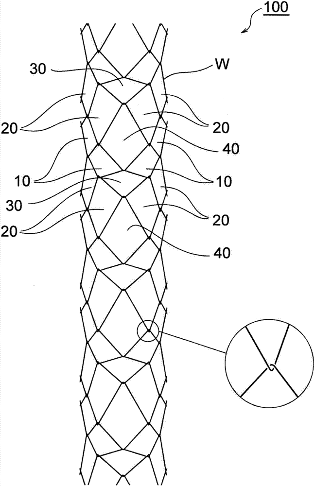
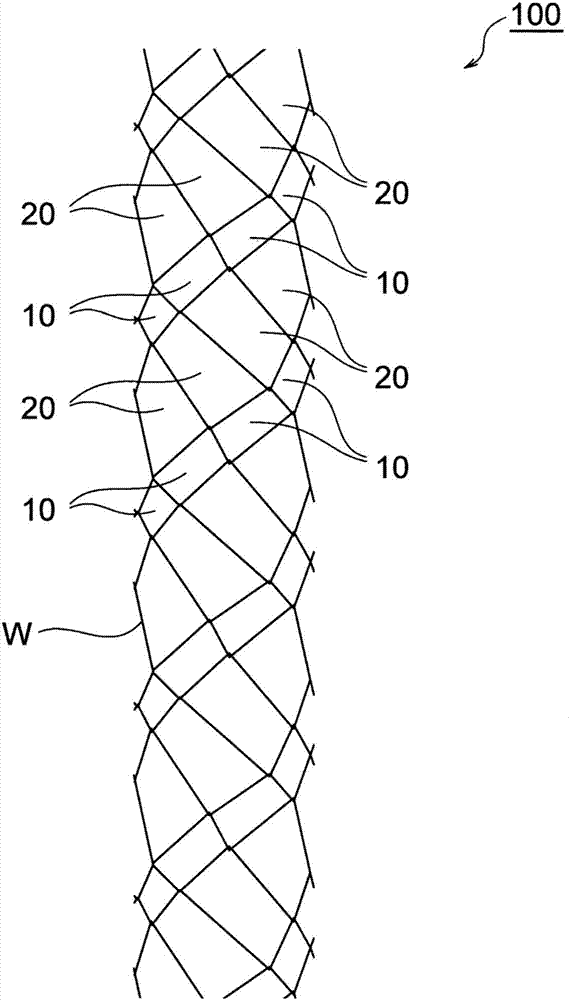
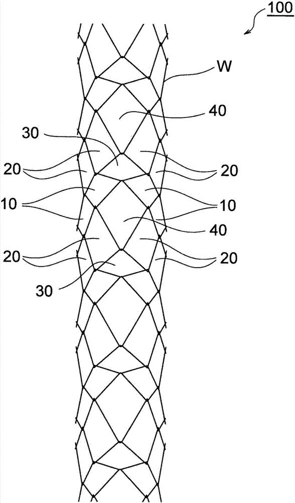
[0044] Figure 1 ~ Figure 3 and Figure 4 ( Figure 4A as well as Figure 4B The stent 100 of this embodiment having the shape shown in ) is, for example, a stent for indwelling in the digestive tract such as the intestine, and is interlocked with each other by making one wire W bend in a wave shape while advancing in the circumferential direction and the axial direction to form a wave shape. (composed in a manner of interlocking with each other) to form a cylindrical mesh pattern.

[0045] In addition, Figure 4 ( Figure 4A as well as Figure 4B The expanded mesh pattern shown by ) is the expanded state (expanded state) of the stent 100 in which no force in the diameter-reducing direction is applied.

[0046] The stent 100 is formed into a cylindrical shape by braiding one wire W.

[0047]As the wire W constituting the stent 100 , a conventionally known wire constituting a stent can be used, preferably a wire composed of a metal material, and a shape memory alloy or the l...


PUM


Abstract

The present invention provides a stent in which a cylindrical mesh pattern is formed by bending a wire (W) into a wave form while advancing in the circumferential direction and the axial direction, and forming a wave-like bending portion interhooked with each other. The stent has alternate The unfolded mesh pattern of the following mesh connection parts is arranged in an orderly manner: the first mesh connection part (10C), which is a first mesh (10) in the approximate parallelogram shape with the interhook part as the apex, sharing the short sides of the parallelogram and connecting with Multiple and constitute; The second mesh connection part (20C), it is the first approximate trapezoid with the shape of the first mesh (10), that is, the long side of the parallelogram as its base and sharing the hook part as the apex. The two meshes (20) share the trapezoidal waist adjacent to the base and are connected to form multiple ones, and no more than three inter-hooks are formed at the same axial position. According to this stent, when the sheath is inserted, the plurality of hook portions do not overlap each other, and the diameter can be sufficiently reduced.

Description

technical field [0001] The present invention relates to a stent for preventing stenosis, obstruction, etc. of a tubular organ by indwelling the tubular organ in the body. Background technique [0002] Stent placement is known in which a stent is indwelled at the site to expand / maintain the lumen when a tubular organ such as the digestive tract or a blood vessel is narrowed / obstructed. [0003] In the stent indwelling operation, after a sheath inserted with a stent in a reduced-diameter state is introduced into a tubular organ to reach a target site (affected site), only the sheath is removed, thereby expanding and indwelling the stent at the target site. [0004] Here, the stent to be indwelled in a tubular organ is constituted by a cylindrical body that is woven by interlocking portions in which the bent portions of the wire rods are bent into waves and advanced in the circumferential and axial directions to form waves. It is formed in a mesh shape (for example, refer to P...

Claims


Application Information

Patent Timeline
Patent Type & Authority Patents(China)
IPC IPC(8): A61F2/90
CPCA61F2/90A61F2230/0026
Inventor 羽贺慎一郎坂井正宗
Owner JAPAN LIFELINE CO LTD
Learn More