
Hydraulic pipe expanding and enlarging device

A pipe expander and hydraulic technology, applied in the field of pipe expanders, can solve the problems of single function of pipe expanders or pipe expanders, need to be configured separately, and high cost of use, and achieve simple and convenient operation, convenient and fast disassembly and assembly, and reduce The effect of sliding frictional resistance

Active Publication Date: 2016-06-22
ZHEJIANG VALUE MECHANICAL & ELECTRICAL PROD CO LTD
View PDF8 Cites 7 Cited by
  • Summary
  • Abstract
  • Description
  • Claims
  • Application Information

AI Technical Summary

Problems solved by technology

[0004] The present invention mainly provides a hydraulic expander and expander with ingenious conception, which integrates the functions of tube expansion and tube expansion, and the conversion of tube expansion or tube expansion functions is convenient and quick, which solves the problem of tube expansion in the prior art. The function of the pipe expander or expander is single, and it needs to be configured separately when used, the cost of use is high, and it brings a lot of inconvenience to the user and other technical problems

Method used


Image

  • Hydraulic pipe expanding and enlarging device
  • Hydraulic pipe expanding and enlarging device
  • Hydraulic pipe expanding and enlarging device

Examples


Embodiment 1

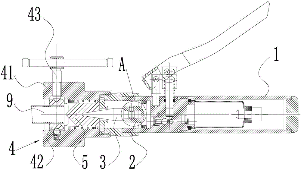
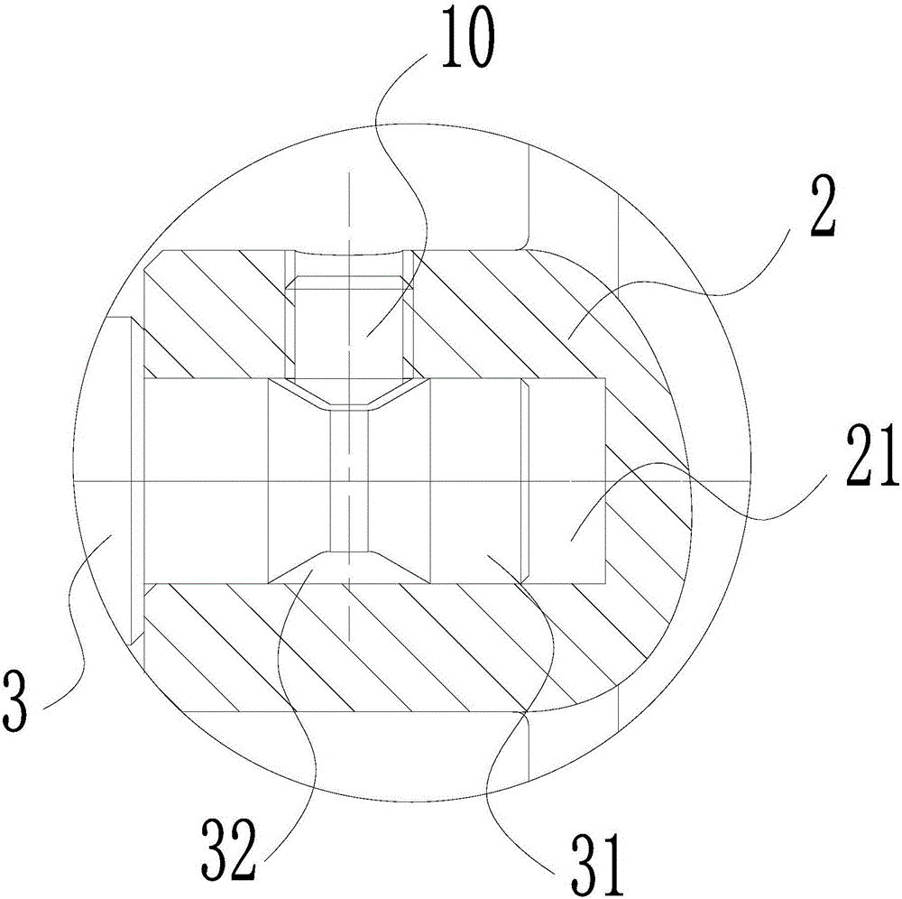
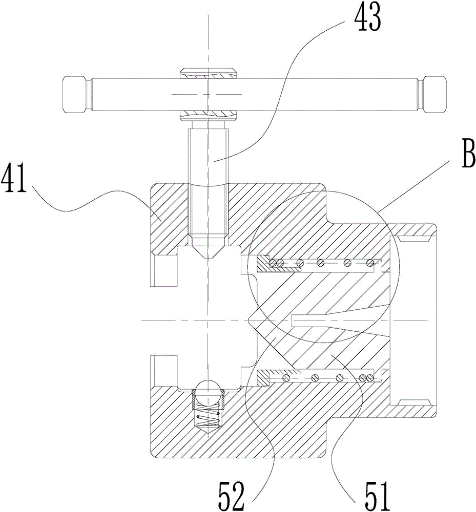
[0021] Such as figure 1 As shown, a hydraulic expander and expander of the present invention includes a circular tubular oil pressure pump 1, a piston 2 is slidably connected to the front port of the oil pressure pump 1, and the expansion tube stem is coaxially connected to the piston 2 3, such as figure 2 As shown, a positioning column 31 is formed by coaxially extending outwardly at the rear end of the expansion tube stem 3 corresponding to the piston 2, and an annular positioning groove 32 is opened on the outer ring surface of the middle part of the positioning column 31, corresponding to the positioning column 31. There is a positioning hole 21 in the middle part of the front end face of the piston 2, and the positioning column 31 is interfitted and inserted in the positioning hole 21, and a positioning stud 10 is screwed radially on the piston 2 corresponding to the annular positioning groove 32, and the positioning stud The inner end of the positioning stud 10 is matc...

Embodiment 2

[0024] After the tube expansion assembly 4 is dismantled as a whole, the expansion tube head is taken and matched with each other at the front end of the expansion tube stem 3 to perform tube expansion processing. All the other parts are identical to Example 1.


PUM


Abstract

The invention discloses a pipe expander and provides a hydraulic pipe expanding and enlarging device. The hydraulic pipe expanding and enlarging device is ingenious in concept, the pipe expanding function and the pipe enlarging function are integrated, and the pipe expanding function or the pipe enlarging function is switched conveniently and fast. Through the hydraulic pipe expanding and enlarging device, the technical problems that in the prior art, a pipe expander or a pipe enlarger is single in function, is needed to be independently arranged during usage, high in usage cost, and brings much inconvenience to a user are solved. The hydraulic pipe expanding and enlarging device comprises an oil hydraulic pump and a piston connected to a front end opening of the oil hydraulic pump in a sliding mode. The piston is connected with a pipe expanding core column capable of being matched with a pipe expanding head mutually. A pipe enlarging assembly is rotationally connected to the front end opening of the oil hydraulic pump. The pipe expanding core column extends into the pipe enlarging assembly. In the pipe enlarging assembly, the corresponding front end of the pipe expanding core column is connected with a pipe enlarging head in an abutted mode, and the pipe enlarging head can move synchronously front and back in the pipe enlarging assembly. The outer ring face of the pipe enlarging head is connected in the pipe enlarging assembly in a mutually matched and sliding mode.

Description

technical field [0001] The invention relates to a pipe expander, in particular to a hydraulic pipe expander and pipe expander which integrates the functions of pipe expansion and pipe expansion, and has convenient and quick conversion of the pipe expansion or pipe expansion functions. Background technique [0002] Pipe expanders and pipe expanders are expanding tools used to expand the inner and outer diameters of pipes in the manufacture and maintenance of various containers, so that the contact parts between the pipe and the tube sheet are tightly bonded, no air leakage and can withstand a certain pressure. However, the existing pipe expanders or pipe expanders often only have a single function, so when pipe expansion and pipe expansion processing are required, it is usually necessary to configure the pipe expander and pipe expander separately, which increases the cost of use and brings many problems to the user. inconvenient. [0003] A Chinese patent discloses a manual ...

Claims


Application Information

Patent Timeline
IPC IPC(8): B21D39/20B21D41/02
CPCB21D39/20B21D41/026
Inventor 蒋友荣
Owner ZHEJIANG VALUE MECHANICAL & ELECTRICAL PROD CO LTD
Learn More