Special stripping machine for motor shell evaporative die

A technology of motor shell and lost foam, which is applied in the direction of loosening model equipment, casting molding equipment, casting molds, etc., which can solve problems such as uneven force, easy to burn hands, and operator hand injuries, so as to prevent lost foam Deformation, avoid injury effect

Inactive Publication Date: 2016-06-22
TAIZHOU HUANGYAN XUANJIE MOLD CO LTD
View PDF6 Cites 3 Cited by
  • Summary
  • Abstract
  • Description
  • Claims
  • Application Information

AI Technical Summary

Problems solved by technology

[0003] After the motor casing lost foam is formed, the traditional method is to manually pull out the inner mold of the lost foam with bare hands. On the one hand, it is easy to burn the hand and cause the o

Method used


Image

  • Special stripping machine for motor shell evaporative die
  • Special stripping machine for motor shell evaporative die
  • Special stripping machine for motor shell evaporative die

Examples


Embodiment Construction

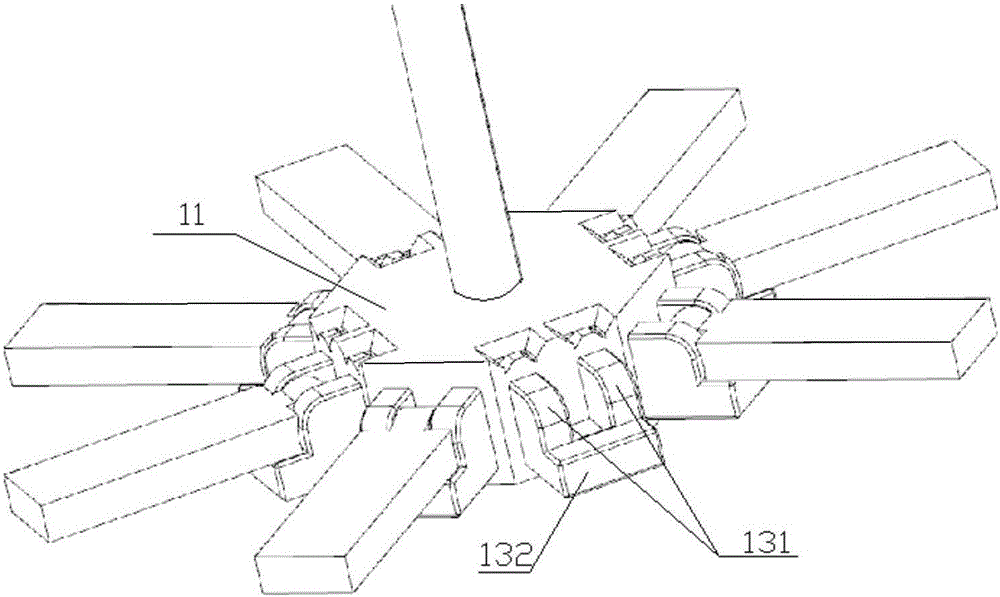
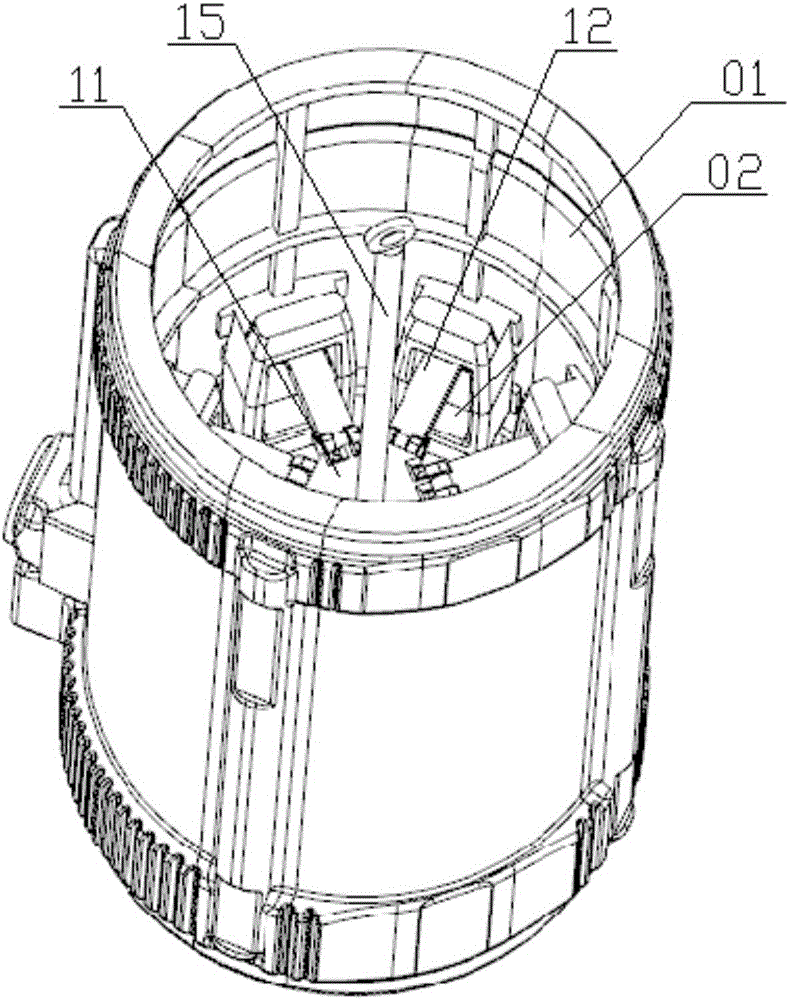
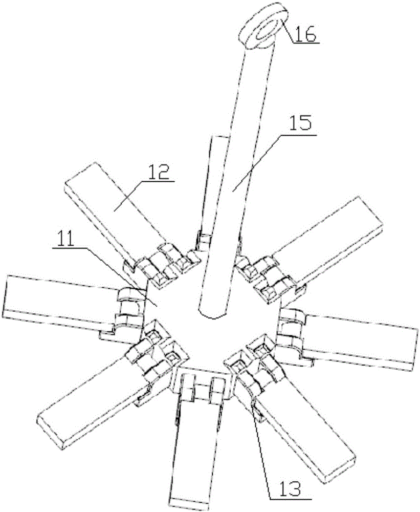
[0023] refer to Figure 1-Figure 7 To further illustrate the present invention, specific specific examples are used to describe the implementation of the present invention. Those skilled in the art can easily understand other advantages and effects of the present invention from the content disclosed in this specification.

[0024] refer to Figure 1-Figure 7 , it should be noted that the structures, proportions, sizes, etc. drawn in the drawings attached to this specification are only used to match the content disclosed in the specification, for those who are familiar with this technology to understand and read, and are not used to limit the implementation of the present invention. Therefore, it has no technical substantive meaning. Any modification of structure, change of proportional relationship or adjustment of size shall still fall within the scope of this invention without affecting the effect and purpose of the present invention. The scope covered by the technical cont...


PUM


Abstract

The present invention relates to the technical field of mold ejectors, in particular to a special ejector for motor shell lost foam, which includes a force-bearing part, and several ejectors are evenly distributed around the force-bearing part; The flap on the stressed part; the flap is hingedly connected with the positioning part arranged on the stressed part. The invention has simple structure and strong practicability.

Description

technical field [0001] The invention relates to the technical field of mold ejectors, in particular to a special ejector for the lost mold of motor shells. Background technique [0002] In the casting process of the motor casing, the lost foam molding process is adopted. The material of the lost foam is polyethylene foam. When casting, because the temperature of the molten iron is high, the mold is melted and burned, and the molten iron fills the cavity. [0003] After the motor casing lost foam is formed, the traditional method is to manually pull out the inner mold of the lost foam with bare hands. On the one hand, it is easy to burn the hand and cause the operator's hand to be injured; on the other hand, pulling it with bare hands leads to uneven force. In turn, the lost foam of the motor shell is easily deformed; finally, the work efficiency is relatively low. Contents of the invention [0004] Aiming at the deficiencies in the prior art, the object of the present inv...

Claims


Application Information

Patent Timeline
IPC IPC(8): B22C9/04B22C19/06B22C7/02
CPCB22C9/043B22C7/02B22C19/06
Inventor 江建新
Owner TAIZHOU HUANGYAN XUANJIE MOLD CO LTD
Why Eureka
Try Eureka