Machining method for spherical water film injection head

A processing method and spray head technology, which are applied to spray devices, spray devices, etc., can solve the problem of inability to spray multiple plane thin water films, and achieve the effect of reducing spray dead angles and meeting process requirements.

Active Publication Date: 2016-06-22
杨阳
View PDF6 Cites 0 Cited by
  • Summary
  • Abstract
  • Description
  • Claims
  • Application Information

AI Technical Summary

Problems solved by technology

[0003] The problem to be solved by the present invention is to provide a processing method for a spherical water film spray head, so as to solve the problem that the existing spray heads cannot spray out multiple planar thin water films

Method used


Image

  • Machining method for spherical water film injection head
  • Machining method for spherical water film injection head
  • Machining method for spherical water film injection head

Examples


Embodiment 1

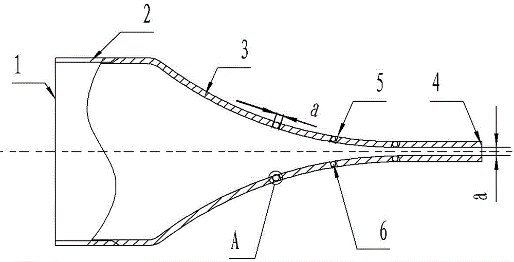
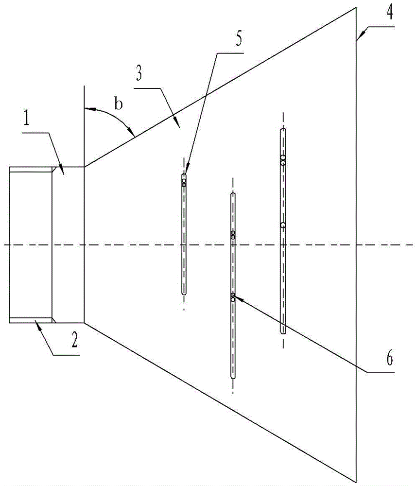
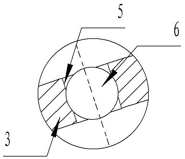
[0015] The processing method of this spherical water film spray head comprises processing a kind of spherical water film spray head, such as figure 1 , figure 2 , image 3 The shown spherical water film spray head includes a spray body, the water outlet end 1 of the spray body is provided with an external thread 2, the spray body is provided with a flat section 3, and the flat section 3 is gradually flattened from near the water inlet end 1 to the water outlet end 4, and the spray One side of the main body is fan-shaped, so that the sprayed water can be flat and thin water film. The inclination angle b of the spray body sector is 60°. The minimum width a of the 4 flat positions of the water outlet end of the jet body, a=0.85 mm, ensures the stability of the water outlet. There are many long holes 5 on the flat section 3, the width of the long holes 5 is a, a=0.85 mm, and multiple plane water films can be sprayed on the flat section 4, so that what the whole spray head spra...

Embodiment 2

[0022] Spherical water film nozzle such as figure 1 , figure 2 , image 3 , as in Example 1. The processing steps include: put cemented carbide powder into the mold for sintering, the mold is equipped with a flat position, a long hole position, and a ball position, and the long hole position is provided with an arc surface partition, and the concave position of the long hole position The groove part is separated from the ball position, and the thickness of the partition plate is 0.15 mm, which is sintered, and then combined with the part with the threaded section for sintering.

[0023] In other embodiments, according to the diameter of the water outlet pipe, the width at the minimum flat position of the water outlet end of the spray head may be any value from 0.6 mm to 1.3 mm. The thickness of the separator in the mold can also be any value between 0.1 mm and 0.2 mm.


PUM

PropertyMeasurementUnit
widthaaaaaaaaaa

Abstract

The invention discloses a machining method for a spherical water film injection head. According to the machining method for the spherical water film injection head, the spherical water film injection head is machined. The spherical water film injection head comprises an injection body. An external thread is arranged at the water outlet end of the injection body. The injection body is provided with a flat section which is gradually flat from the position close to the water inlet end to the water outlet end. One surface of the injection body is in a fan shape. The inclined angle of the fan shape of the injection body is 60 degrees. A plurality of long holes are formed in the flat section. The middle of each long hole is provided with at least one ball through a groove in the wall of the long hole. The machining method comprises the steps that a hard alloy powder material is put into a mold and sintered, the mold is internally provided with flat positions, long hole positions and ball positions, the long hole positions are provided with cambered surface partition plates, and sintering is conducted. Compared with the prior art, the machining method for the spherical water film injection head is capable of solving the problem that an existing injection head cannot inject a plurality of plane type thin water films.

Description

technical field [0001] The invention relates to the technical field of plumbing equipment manufacturing, in particular to a method for processing a spray head capable of spraying out multiple planar water films and annular water films. Background technique [0002] The existing processing methods of spherical water film nozzles generally include base pipes, which are connected by screws. The nozzles are cylindrical, and the sprayed water is a water column. The thin water film, and the existing injection pipe fittings can't spray multi-channel flat thin water film. Thereby need to design a kind of injection pipe fitting that can spray water film, in order to satisfy the deficiency of market. The processing method of the spherical water film spray head is the processing method of the spray head which sprays out the water film. Contents of the invention [0003] The problem to be solved by the present invention is to provide a processing method for a spherical water film sp...

Claims


Application Information

Patent Timeline
Patent Type & Authority Applications(China)
IPC IPC(8): B23P15/00B05B1/00
CPCB05B1/00B23P15/00
Inventor 谭晓云
Owner 杨阳
Why Eureka
Try Eureka