Portable Left Half Shaft Flange Bearing Installation Tool for Automatic Transmission Remanufacturing

A technology for automatic transmissions and installation tools, which is applied in the direction of manufacturing tools, metal processing, metal processing equipment, etc., can solve the problems of inconvenient support flanges, etc., and achieve the effects of not easy to damage, fast installation speed, and convenient installation

Active Publication Date: 2017-11-07
苏州盛泽科技创业园发展有限公司
View PDF8 Cites 2 Cited by
  • Summary
  • Abstract
  • Description
  • Claims
  • Application Information

AI Technical Summary

Problems solved by technology

[0003] The invention provides a portable left half shaft flange bearing installation tool for automatic transmission remanufacturing, which can conveniently install the bearing between the left half shaft and the flange, and solves the problem of installing the bearing in the remanufacturing process of the automatic transmission. Inconvenient problem when going to the left half shaft to support the flange

Method used


Image

  • Portable Left Half Shaft Flange Bearing Installation Tool for Automatic Transmission Remanufacturing
  • Portable Left Half Shaft Flange Bearing Installation Tool for Automatic Transmission Remanufacturing
  • Portable Left Half Shaft Flange Bearing Installation Tool for Automatic Transmission Remanufacturing

Examples


Embodiment 1

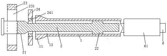
[0029] Embodiment one, see figure 1 , a portable left half-shaft flange bearing installation tool for automatic transmission remanufacturing, comprising a push rod 1. The right end of the push rod 1 is provided with a grip bar 6 . 6 sets of grip bars are provided with handle gloves 61 . The handle glove 61 is a rubber sheath. The left end of the push rod 1 is provided with a striking section 11 . An avoidance hole 12 is provided in the push rod 1 . The escape hole 12 runs through the end surface of the striking section 11 . The escape hole 12 extends along the length direction of the push rod 1 . The left end of the left half shaft 2 is provided with a bearing support section 21 , and the right end is provided with a large diameter section 22 . The diameter of the large-diameter section 22 is smaller than that of the bearing support section 21 . The flange 23 is provided with a shaft hole 231 for installing the bearing 24 . The bearing 24 is provided with an inner ring...

Embodiment 2

[0034] Embodiment two, the difference with embodiment one is;

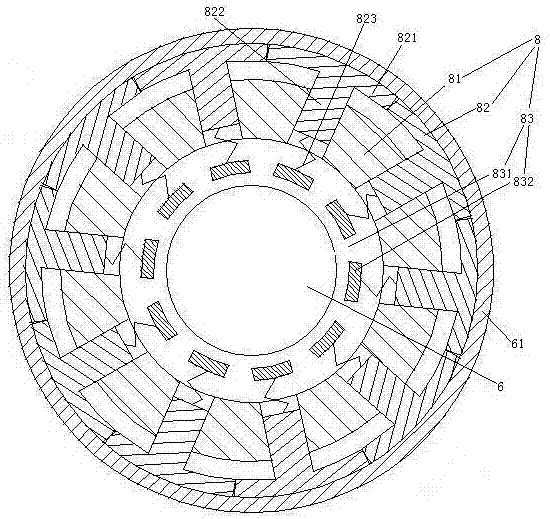
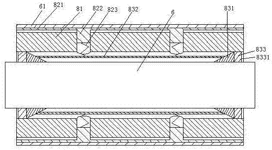
[0035] see Figure 4 , The push rod 1 is also provided with a bearing dismounting booster mechanism 9. The bearing disassembly and assembly booster mechanism 9 includes a blower fan 91 , an air duct 92 and a wind direction conversion mechanism 93 . The fan 91 is provided with an air inlet 911 and an air outlet 912 . The fan 91 includes fan blades 913 and a motor 914 for driving the fan blades. The air duct 92 is an annular structure. The air duct 92 communicates with the air inlet 911 and the air outlet 912 . The air duct 92 is provided with an entrance and exit passage 921 , an entrance passage 922 and an exit passage 923 . The access road 921 runs through to the push ring 14 . The entrance and exit passage 921 is provided with an annular cylinder 924 extending circumferentially along the knocking section 11 . The annular cylinder body 924 is sealed and slidably connected with an annular thimble driving pi...


PUM


Abstract

The invention relates to the technical field of remanufacturing of automatic transmissions. A conveniently-held left half shaft flange bearing installation tool for remanufacturing of an automatic transmission is characterized by comprising a pushing rod; a knocking section is arranged at one end of the pushing rod, and the diameter of the knocking section is smaller than that of a shaft hole, used for installation of a bearing, of a flange; a receding hole which penetrates through the end surface of the knocking section, extends in the length direction of the pushing rod and allows a left half shaft to be inserted therein is arranged in the pushing rod, and the diameter of the receding hole is smaller than the outer diameter of an inner ring of the bearing; and a handheld rod is arranged at the other end of the pushing rod. By means of the conveniently-held left half shaft flange bearing installation tool for remanufacturing of the automatic transmission, the bearing can be conveniently installed between the left half shaft and the flange, and the problem that in the remanufacturing process of the automatic transmission, the bearing is inconvenient to install on the left half shaft to support the flange is solved.

Description

technical field [0001] The invention relates to the technical field of automatic transmission remanufacturing, in particular to a portable left half-shaft flange bearing installation tool for automatic transmission remanufacturing. Background technique [0002] The left half shaft is a part of the automatic transmission, and one end of the left half shaft is supported by a flange through a bearing. In the process of rebuilding the transmission, it is necessary to install the flange bearing between the shaft hole of the flange and the left half shaft to realize the rotational connection of the flange to one end of the left half shaft. The end away from the separation of the half shaft is loaded with bearings. The existing method of installing the flange bearing of the left half shaft is to use a hammer to change the knocking position along the circumferential direction of the bearing to drive the bearing to move along the axial direction of the left half shaft. Due to the sm...

Claims


Application Information

Patent Timeline
Patent Type & Authority Patents(China)
IPC IPC(8): B23P19/02B23P19/033
CPCB23P19/02B23P19/033
Inventor 危金兰
Owner 苏州盛泽科技创业园发展有限公司
Why Eureka
Try Eureka