A jig for finishing machining of ultra-thin shaft parts

A shaft part, ultra-thin technology, applied in the direction of manufacturing tools, metal processing equipment, metal processing machinery parts, etc., can solve the problems of radial deformation, weak strength, poor rigidity of thin-walled parts, etc., to eliminate thermal deformation, The effect of improving production efficiency and improving product qualification rate

Inactive Publication Date: 2017-06-23
YANTAI NANSHAN UNIV
View PDF8 Cites 0 Cited by
  • Summary
  • Abstract
  • Description
  • Claims
  • Application Information

AI Technical Summary

Problems solved by technology

However, the technical solution disclosed in this patent is to adjust the axial displacement of the nut so that the conical slope produces a radial force on the thin-walled parts. A very small radial variable can generate a huge radial force, but Since the inner cavity surface of the thin-walled parts and the contact surface of the tapered slope are not in full contact but only partly in contact, and the thin-walled parts themselves have poor rigidity and weak strength, this uneven radial force may make it Radial deformation occurs, even if there is no deformation, a certain stress is produced, which is contrary to the original intention of the present invention

Method used


Image

  • A jig for finishing machining of ultra-thin shaft parts

Examples


Embodiment Construction

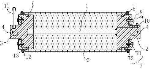
[0011] Such as figure 1 As shown, it is a fixture for finishing machining of ultra-thin shaft parts according to the present invention, which includes a mandrel 1, one end of the mandrel is fixedly connected to the center of the inner end surface of the first flange 2, and the other end of the mandrel is provided with an outer thread, the external thread matches the threaded hole provided in the center of the inner end face of the second flange 3, the first flange 2 and the second flange 3 include a three-step circular platform, and the top hole 4 is set on the end surface of the first circular platform , a rubber ring 5 is sleeved on the outer circumference of the second-order round platform, four threaded holes are uniformly arranged on the end surface of the second-order round platform, and the outer diameter of the outer circumference of the third-order round platform is smaller than the ultra-thin shaft parts 6 The inner diameter of the second-stage circular platform is 1...


PUM


Abstract

The invention relates to an ultrathin shaft part finish turning clamp which comprises a mandrel. A first flange is fixedly connected with one end of the mandrel, and the other end of the mandrel is in threaded fit with a second flange. Each of the first flange and the second flange comprises three steps of circular truncated cones. A center hole is formed in the end surface of each first step of circular truncated cone. A rubber ring sleeves the circumferential excircle of each second step of circular truncated cone. More than three threaded holes are uniformly formed in the end surface of each second step of circular truncated cone. The external diameter of the circumferential excircle of each third step of circular truncated cone is 1-2 mm smaller than the internal diameter of an ultrathin shaft part. A press plate sleeves each second step of circular truncated cone. Center holes of the press plates sleeve the first steps of circular truncated cones. More than three through holes are uniformly formed in the side wall of each press plate. Bolts pass through the through holes and then are matched with the threaded holes in the end surfaces of the second steps of circular truncated cones so as to enable the outer edges of the side walls of the press plates to be propped against the outer sides of the rubber rings. An oil circuit used for communicating the inner end of the first flange with a nozzle arranged on the circumferential excircle of the first step of circular truncated cone is arranged on the first flange. A shift rod is arranged on the first step of circular truncated cone of the second flange. Compared with the prior art, the ultrathin shaft part finish turning clamp has the advantages that the rigidity of the ultrathin shaft part is enhanced, and the thermal deformation is eliminated.

Description

technical field [0001] The invention relates to the technical field of mechanical processing, in particular to a jig for finishing machining of ultra-thin shaft parts. Background technique [0002] Thin-walled parts have been increasingly widely used in various industrial sectors. It has the characteristics of light weight, material saving, and compact structure. However, the processing of thin-walled parts is a difficult problem in turning. The reason is that thin-walled parts have poor rigidity and weak strength. [0003] Factors Affecting the Processing Accuracy of Thin-walled Parts 1. Susceptibility to force deformation: due to the thin wall of the workpiece, it is easy to deform under the action of clamping force, thereby affecting the dimensional accuracy and shape accuracy of the workpiece; Cutting heat will cause thermal deformation of the workpiece, making it difficult to control the size of the workpiece; 3. Easy to vibrate and deform: under the action of cutting ...

Claims


Application Information

Patent Timeline
Patent Type & Authority Patents(China)
IPC IPC(8): B23Q3/00B24B41/06
CPCB23Q3/00B23Q2703/10B24B41/062
Inventor 隋信举史文杰周天胜张金道
Owner YANTAI NANSHAN UNIV
Why Eureka
Try Eureka