Clamp

A fixture and splint technology, which is applied in the direction of clamping, manufacturing tools, workpiece clamping devices, etc., can solve problems such as warping and easy inclination of workpieces to be processed, and achieve the effect of eliminating defective products and improving product qualification rate

Inactive Publication Date: 2016-06-22
SUZHOU HEYER PRECISION CO LTD
View PDF10 Cites 6 Cited by
  • Summary
  • Abstract
  • Description
  • Claims
  • Application Information

AI Technical Summary

Problems solved by technology

[0003] The purpose of the present invention is to overcome the deficiencies in the prior art and provide a fixture to solve the technical problem in the prior art that the fixture only fixes the workpiece to be processed in the horizontal direction, but the workpiece to be processed in the vertical direction is prone to tilting and warping

Method used


Image

  • Clamp

Examples


Embodiment Construction

[0014] The present invention will be further described below in conjunction with the accompanying drawings. The following examples are only used to illustrate the technical solution of the present invention more clearly, but not to limit the protection scope of the present invention.

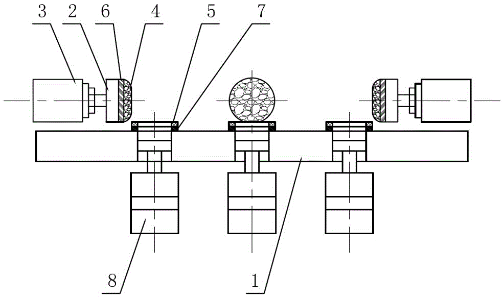
[0015] Such as figure 1 As shown, the structural schematic diagram of the present invention includes a workbench 1 for placing workpieces to be processed and a plurality of splints 2 for fixing the workpieces to be processed in the horizontal direction. As a preferred solution of the present invention, four splints 2 are provided, and the four splints 2 form a square and are distributed around the workpiece to be processed. The back of each splint 2 is respectively connected with a controllable cylinder 3 for controlling the stroke of the splint 2, and multiple splints 2 cooperate to clamp the workpiece to be processed. Second pressure sensors 6 are provided on the working surfaces where the ...


PUM


Abstract

The invention discloses a clamp which comprises a worktable and a plurality of clamping plates. The back of each clamping plate is connected with a controllable air cylinder. A plurality of suction nozzles longitudinally penetrating the worktable are formed in the worktable. Each vacuum suction nozzle is connected with a vacuum pump. The periphery of each vacuum suction nozzle is further provided with a first pressure sensor. The controllable air cylinders, the vacuum pumps and the first pressure sensors are in signal connection with a controller. The controller pushes a clamping plate to clamp a workpiece to be machined in the horizontal direction through the controllable air cylinders, meanwhile, the controller controls the air pressure of the vacuum pumps according to signals output by the first pressure sensors, and the workpiece to be machined is pressed in the vertical direction through the vacuum pumps. The pressing condition of the workpiece to be machined in the vertical direction is judged according to the signals output by the first pressure sensors, the flatness of the lower surface of the workpiece to be machined can be judged, inferior-quality products can be removed as soon as possible, and the product qualification rate is increased.

Description

technical field [0001] The invention relates to a clamp. Background technique [0002] In the process of mechanical production and manufacturing, it is usually encountered in processing the surface of the workpiece. The existing fixture includes a workbench and three baffles on the workbench, and the baffles can be fixed at various positions relative to the workbench. The above fixture only positions the product in the horizontal direction, but does not position the product in the vertical direction. During processing, there will be a certain degree of vibration in the vertical direction, which will cause the workpiece to be processed to be tilted or twisted in the vertical direction, which is not conducive to the processing of the workpiece. In addition, for workpieces to be processed with flatness requirements on the bottom surface, the workpieces to be processed may also be deformed after being clamped by the fixture. If the detection and elimination cannot be carried ou...

Claims


Application Information

Patent Timeline
Patent Type & Authority Applications(China)
IPC IPC(8): B25B11/00B23Q3/08
CPCB25B11/00B23Q3/08B23Q3/088B25B11/005
Inventor 黄文卿
Owner SUZHOU HEYER PRECISION CO LTD
Why Eureka
Try Eureka