Extractor hood with high-efficiency trapping function

A range hood, high-efficiency technology, applied in the field of high-efficiency capture range hoods, can solve problems such as closing doors and windows, indoor pollution, side escape of range hoods, etc., to prevent oil fume from escaping, reduce noise and energy Consumption, to avoid the effect of frontal escape

Inactive Publication Date: 2021-01-26
TIANJIN UNIV
View PDF6 Cites 0 Cited by
  • Summary
  • Abstract
  • Description
  • Claims
  • Application Information

AI Technical Summary

Problems solved by technology

The extraction process of the range hood can be regarded as a point-sink type suction. Theoretically, the greater the exhaust air volume, the higher the efficiency. Properly increasing the air volume can help improve the effect of the range hood. However, due to the national requirements for building energy conservation, The airtightness of the building envelope is getting better and better. At the same time, due to the influence of cooking habits and outdoor air quality, doors and windows are often closed during the cooking process, which leads to the fact that the natural supplementary air often cannot meet the supplementary air requirements of the kitchen exhaust system. At the same time, due to the influence of wind pressure in the air duct of high-rise buildings, the range hood used in the actual home cannot reach the rated air volume marked; at the same time, when the window is opened during actual use, the unstable air flow outside will It has a great impact on the collection efficiency of the range hood. Due to the interference of the ambient air flow (including personnel walking, etc.), the effect of the range hood will be greatly reduced, resulting in serious indoor pollution; in addition, the collection of the range hood The energy efficiency area is g

Method used


Image

  • Extractor hood with high-efficiency trapping function
  • Extractor hood with high-efficiency trapping function
  • Extractor hood with high-efficiency trapping function

Examples


Example Embodiment

[0018] The present invention will be described in detail below in conjunction with specific embodiments and accompanying drawings.

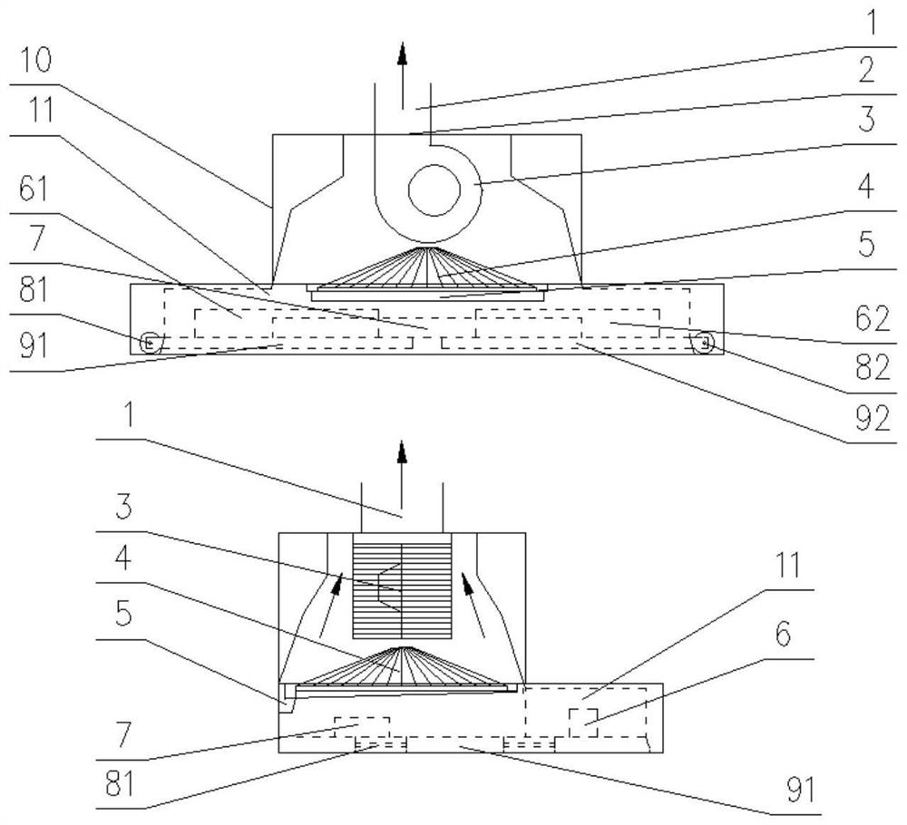
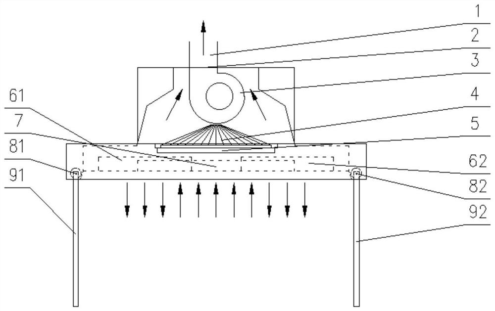
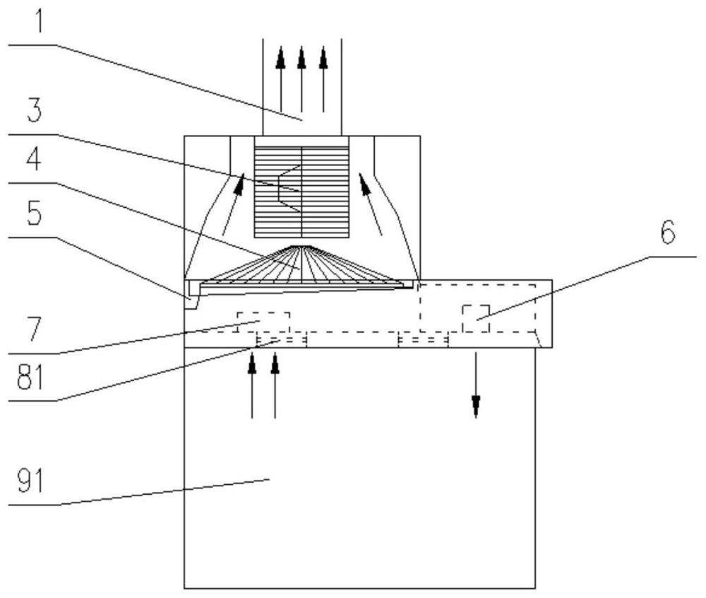
[0019] As shown in the accompanying drawings, a high-efficiency collection range hood of the present invention includes a range hood housing 10, an inner shell 11 is installed in the range hood housing 10, and the inner shell 11 Both sides of the shell 11 are provided with supplementary air outlets 61 and 62, which can be driven by a cross-flow fan 6, and an air suction port 7 is provided near the wall of the range hood housing 10; Net 4, oil collecting groove 5, are used for collecting the oil that oil leakage net leaks down. The motor 12 is installed in the range hood housing 10, and the baffle is driven to open and close with the power-on state through the connecting rod 13 and the transmission rods 141 and 142 on both sides, and hinges 81 are respectively installed on both sides of the range hood housing 10. , 82, link to each other with baf...


PUM


Abstract

The invention discloses an extractor hood with a high-efficiency trapping function. The extractor hood comprises an extractor hood shell capable of being installed on a side wall, an inner shell is installed in the extractor hood shell, air supplementing openings are formed in the inner shell and can be driven by a cross-flow draught fan, and meanwhile an air suction opening is formed in the side,close to the wall, of the extractor hood shell. An oil leakage net and an oil collecting tank are arranged above the air suction opening. A motor is installed in the extractor hood shell, baffles aredriven by a connecting rod and transmission rods to be opened and closed along with the opening state, and hinges are installed on the two sides of the extractor hood shell and connected with the baffles. An air discharging port is formed in the top of the extractor hood shell, a smoke exhaust fan is installed in the extractor hood shell, and an air outlet of the smoke exhaust fan communicates with an inlet of an air exhaust pipeline penetrating through the air discharging port. According to the extractor hood with the high-efficiency trapping function, to achieve the same trapping effect, the required air discharging amount needed in the smoke exhaust manner is greatly reduced, correspondingly, noise and energy consumption can be reduced, and the purposes of energy conservation, emissionreduction and noise reduction are achieved.

Description

technical field [0001] The invention relates to a range hood, in particular to a high-efficiency collection range hood. Background technique [0002] With the modern development of the city, range hoods are installed in almost all urban residential kitchens. The extraction process of the range hood can be regarded as a point-sink type suction. Theoretically, the greater the exhaust air volume, the higher the efficiency. Properly increasing the air volume can help improve the effect of the range hood. However, due to the national requirements for building energy conservation, The airtightness of the building envelope is getting better and better. At the same time, due to the influence of cooking habits and outdoor air quality, doors and windows are often closed during the cooking process, which leads to the fact that the natural supplementary air often cannot meet the supplementary air requirements of the kitchen exhaust system. At the same time, due to the influence of wind...

Claims


Application Information

Patent Timeline
IPC IPC(8): F24C15/20
CPCF24C15/2035
Inventor 刘俊杰刘智琳
Owner TIANJIN UNIV
Why Eureka
Try Eureka