Transmission front assembly detachment tool which is used for remanufacturing of automatic transmission and provided with handle

A technology for automatic transmission and disassembly tools, which is applied to manufacturing tools, hand-held tools, etc., can solve problems such as damage, high noise, inconvenience, etc., and achieve the effect of good reliability and low noise

Active Publication Date: 2016-06-22
YANCHENG HAITE MACHINERY TECH CO LTD
View PDF7 Cites 6 Cited by
  • Summary
  • Abstract
  • Description
  • Claims
  • Application Information

AI Technical Summary

Problems solved by technology

[0003] The invention provides a front assembly removal tool with a handle for automatic transmission remanufacturing, which can disassemble the cylindrical part sleeved on the shaft in the front assembly of the transmission with low noise, smoothly and conveniently, and solves the problem of disassembling the transmission. The cylindrical parts on the front assembly are noisy, inconvenient and prone to damage

Method used


Image

  • Transmission front assembly detachment tool which is used for remanufacturing of automatic transmission and provided with handle
  • Transmission front assembly detachment tool which is used for remanufacturing of automatic transmission and provided with handle
  • Transmission front assembly detachment tool which is used for remanufacturing of automatic transmission and provided with handle

Examples


Embodiment 1

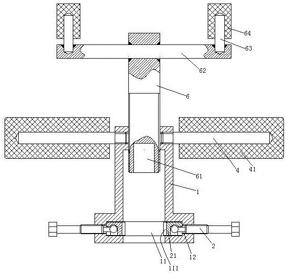
[0031] Embodiment one, see figure 1 , a transmission front assembly removal tool with a handle for automatic transmission remanufacturing, comprising a sleeve 1 . The lower end of the inner peripheral surface of the sleeve 1 is provided with an annular groove 11 . The annular groove 11 is provided with two threaded holes 12 . The threaded hole 12 runs through the sleeve 1 . The threaded holes 12 are symmetrically distributed on both radial sides of the sleeve 1 . The threaded hole 12 is threadedly connected with the clamping rod 2 . The inner end of the clamping rod 2 is clamped with a clamping block 21 . The clamping block 21 and the clamping rod 2 are rotatably connected together. The clamping block 21 has an arc-shaped clamping surface 211 . The axis of the clamping surface 211 is parallel to the axis of the sleeve 1 . The depth of the sleeve 1 is symmetrically provided with two holding rods 4 . The grip bar 4 is perpendicular to the sleeve 1. 4 sets of grip bars a...

Embodiment 2

[0034] Embodiment two, the difference with embodiment one is:

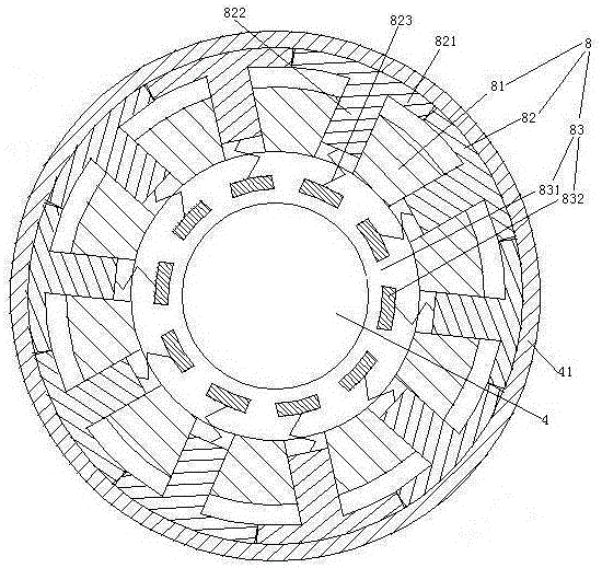
[0035] see image 3 , An elastic adjustment mechanism 8 is provided between the grip bar 4 and the handle cover 41 . The elastic force adjustment mechanism 8 includes a base pipe 81 , a clamping layer 82 and a preload adjustment structure 83 . The base pipe 81 is sheathed outside the handle bar 4 . The base pipe 81 is passed through the handle glove 41 . The clamping layer 82 is composed of several friction strips 821 . The friction strips 821 are distributed along the circumferential direction of the base pipe 81 . The friction strip 821 is provided with a plurality of slide bars 822 axially distributed along the radial extension of the base pipe. The sliding rod 822 slides through the base tube 81 . The inner end of the sliding rod 822 is provided with a third spring 823 . The third spring 823 drives the friction strip to abut against the handle glove 41 through the slide bar. The outwardly moving preloa...

Embodiment 3

[0038] Embodiment three, the difference with embodiment two is:

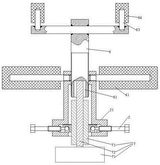
[0039] see Figure 5 , also includes motor 5 and power switching mechanism 9. The motor 5 includes a motor housing 51 and a motor shaft 52 . The motor housing 51 is fixedly connected with the driving arm 62 . The motor casing 51 is provided with the connection terminal 3 . The push rod 6 is connected to one end of the motor shaft 52 through a reducer 53 . The other end of the motor shaft 52 passes through the driving arm 62 .

[0040] see Figure 6 , The power switching mechanism 9 includes a switch 91 , a pressing rod 92 , a latch 93 and an insertion spring 94 . The switch 91 and the pressing rod 92 are located on both sides of the latch 93 . The switch 91 is fixed inside the drive arm 62 . Switch 91 is a push switch, because the control motor 5 starts and stops. The pressing rod 92 passes through the driving arm 62 . The pin 93 is slidably connected in the driving arm 62 . The motor shaft 52 is prov...


PUM


Abstract

The invention relates to the technical field of remanufacturing of automatic transmissions. A transmission front assembly detachment tool which is used for remanufacturing of an automatic transmission and provided with a handle comprises a sleeve. One end of the sleeve is in threaded connection with a clamping rod extending into the sleeve, and the other end of the sleeve is in threaded connection with an ejection rod. A clamping block is rotationally connected with the inner end of the clamping rod in a clamped mode. One end of the ejection rod extends into the sleeve in the axial direction of the sleeve, and the other end of the ejection rod is provided with a driving arm. The sleeve is provided with a holding rod, and the holding rod is provided with a handle sleeve. By means of the transmission front assembly detachment tool which is used for remanufacturing of the automatic transmission and provided with the handle, a cylindrical part, arranged on a shaft in a sleeving mode, of a transmission front assembly can be detached stably and conveniently with low noise, and the problem that detachment of the cylindrical part on the transmission front assembly is high in noise, inconvenient and prone to damage is solved.

Description

technical field [0001] The invention relates to the technical field of remanufacturing of automatic transmissions, in particular to a dismantling tool for front assembly of a transmission with a handle for remanufacturing of automatic transmissions. Background technique [0002] The front assembly of the transmission includes a front assembly body, a shaft arranged on the front assembly body and a cylindrical component sleeved on the shaft. It is sometimes necessary to remove the cylindrical part from the shaft during rebuilding of an automatic transmission. The removal of the cylindrical component in the existing automatic transmission rebuilding process is achieved by hitting the cylindrical component to move it along the axial direction of the shaft. It is noisy and inconvenient to disassemble by beating, and it is also easy to knock out the cylindrical parts. Contents of the invention [0003] The invention provides a front assembly removal tool with a handle for aut...

Claims


Application Information

Patent Timeline
Patent Type & Authority Applications(China)
IPC IPC(8): B25B27/02
CPCB25B27/023
Inventor 何子军
Owner YANCHENG HAITE MACHINERY TECH CO LTD
Why Eureka
Try Eureka