Pin shaft feeding device

A technology of feeding device and pin shaft, which is applied in the direction of conveyor objects, transportation and packaging, etc., can solve the problems of high labor intensity of workers, secondary damage of workpieces, and low work efficiency, so as to improve sales efficiency, increase success rate, and labor low intensity effect

Inactive Publication Date: 2016-06-22
HEFEI UNIV OF TECH
View PDF6 Cites 0 Cited by
  • Summary
  • Abstract
  • Description
  • Claims
  • Application Information

AI Technical Summary

Problems solved by technology

Among them, the pin feeding device is an important part of the pin threading process. At this stage, the pin feeding is all manual or semi-automatic equipment, resulting in low work efficiency, high labor intensity, and high production costs for the enterprise. At the same time, it will make the workpiece Secondary damage to workpieces due to improper handling by workers or other human factors

Method used


Image

  • Pin shaft feeding device
  • Pin shaft feeding device
  • Pin shaft feeding device

Examples


Embodiment Construction

[0026] The embodiments of the present invention are described in detail below. This embodiment is implemented on the premise of the technical solution of the present invention, and detailed implementation methods and specific operating procedures are provided, but the protection scope of the present invention is not limited to the following implementation example.

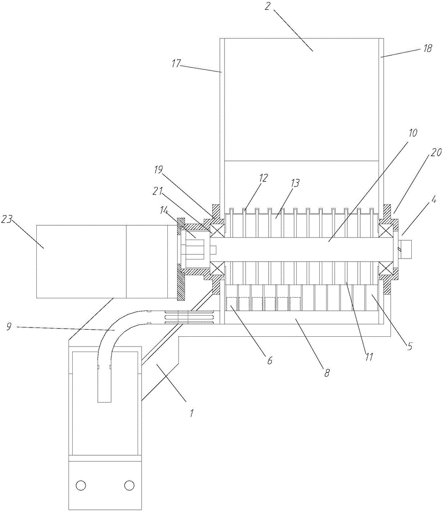
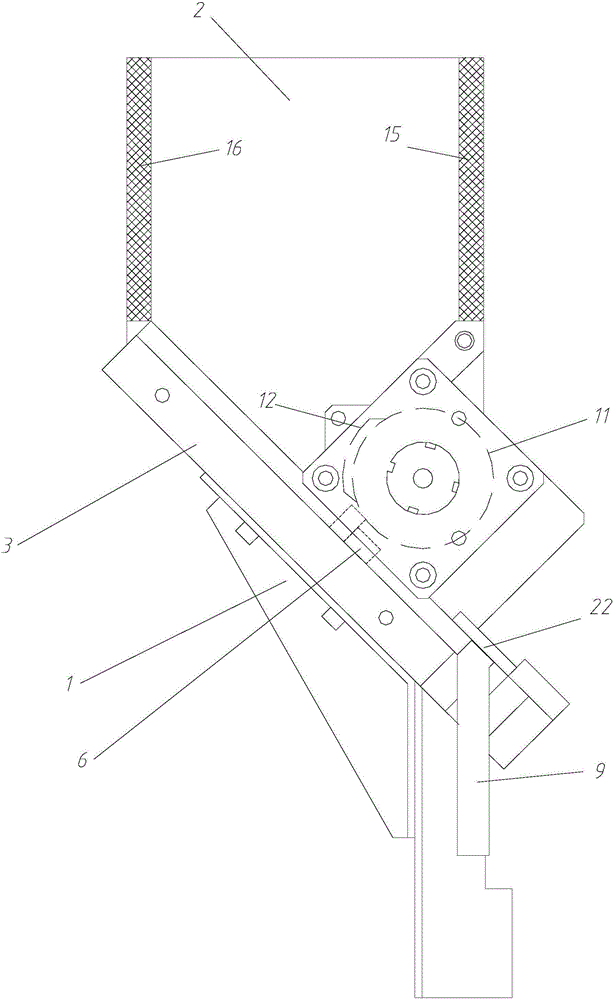
[0027] see Figure 1 to Figure 4 , this embodiment discloses a pin shaft feeding device, comprising a frame 1 and a material box 2, a chute plate 3 and a fork mechanism 4 respectively arranged on the frame 1, the bottom of the material box 2 is open at the bottom, and the chute plate 3 is set At the opening at the bottom of the material box 2, and the front end of the chute plate 3 is inclined downwards, the chute plate 3 is provided with a plurality of side-by-side chutes 5, the width of the chute 5 is just the diameter that can accommodate a bearing pin 6, The shifting fork mechanism 4 is arranged between the ma...


PUM


Abstract

The invention discloses a pin shaft feeding device. The pin shaft feeding device comprises a rack, a feed box, a chute plate and a shifting fork mechanism, and the feed box, the chute plate and the shifting fork mechanism are arranged on the rack. The chute plate is arranged at the position of an opening in the bottom of the feed box, and the front end of the chute plate is obliquely arranged downwards. The chute plate is provided with a plurality of sliding grooves arranged side by side. The width of the sliding grooves is large enough to be right equal to the diameter of a pin shaft. The shifting fork mechanism is arranged between the feed box and the chute plate and used for arranging pin shafts on the chute plate in sequence. A transverse groove is formed in the front end of the chute plate, a push plate parallel to the chute plate is arranged in the transverse groove, and the push plate is driven by a second drive mechanism to move back and forth in the left-and-right direction. A feeding pipe is arranged on one side of the chute plate, and the end of the feeding pipe communicates with the transverse groove of the chute plate. Compared with the prior art, the pin shaft feeding device has the following beneficial effects that by means of rotation of the shifting fork mechanism, automatic and orderly pin shaft feeding is achieved, the situation that the pin shafts are still in a disorderly scattering state after entering chutes is avoided, and the automation degree is high.

Description

technical field [0001] The invention relates to a feeding device, in particular to a pin shaft feeding device. Background technique [0002] The rocker arm of the motorcycle needs to send the pin shaft to the designated position before threading, and then the threading process is completed by the threading mechanism. [0003] At present, domestic and foreign rocker arm riveting production lines are developing in the direction of automation, high efficiency, and fewer people. As an important part of the rocker arm production line, the threading process plays a vital role in realizing automation and improving production efficiency. Among them, the pin feeding device is an important link in the pin threading process. At present, the pin feeding is all manual or semi-automatic equipment, resulting in low work efficiency, high labor intensity, and high production costs for the enterprise. Secondary damage to workpieces due to improper handling by workers or other human factors....

Claims


Application Information

Patent Timeline
IPC IPC(8): B65G47/82
CPCB65G47/82
Inventor 何高清胡思杰韩春明祖晅包明帝
Owner HEFEI UNIV OF TECH
Why Eureka
Try Eureka