Vacuum chamber roof lifting device

A technology of jacking device and vacuum chamber, which is applied in the direction of lifting device, lifting frame, etc., to achieve the effect of high equipment efficiency, simple equipment, safe and reliable equipment

Inactive Publication Date: 2016-06-22
WISDRI ENG & RES INC LTD
View PDF5 Cites 0 Cited by
  • Summary
  • Abstract
  • Description
  • Claims
  • Application Information

AI Technical Summary

Problems solved by technology

Due to the diversity of vacuum chamber layout forms, the replacement methods of vacuum chambers are also different, and different vacuum chamber replacement methods have their own advantages and disadvantages in terms of RH production, floor space, investment costs, production scheduling, etc.

Method used


Image

  • Vacuum chamber roof lifting device
  • Vacuum chamber roof lifting device
  • Vacuum chamber roof lifting device

Examples


Embodiment Construction

[0024] The technical solutions of the present invention will be further described in detail through the following embodiments in conjunction with the accompanying drawings. Apparently, the described embodiments are only partial embodiments of the present invention.

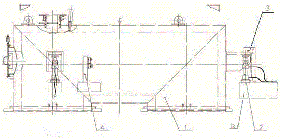
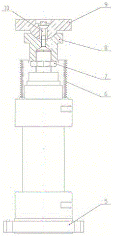
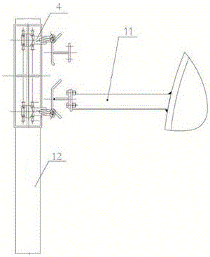
[0025] Such as Figure 1~3 As shown, a device for lifting the top of the vacuum chamber includes a vacuum chamber top 1, and also includes an oil cylinder 2, a travel switch 4 and a hydraulic control system; the oil cylinder 2 is fixedly installed on the jacking platform 13; the travel switch 4 and The hydraulic control system is interlocked.

[0026] Specifically in this example, three oil cylinders are arranged on the top 1 of the vacuum chamber to ensure the stability of the movement. Three oil cylinders 2 control the lifting of the top 1 of the vacuum chamber through a hydraulic power source. The oil cylinder 2 requires special order, the lower part of the oil cylinder 2 is fixed on the jacking platform 7 th...


PUM


Abstract

The invention discloses a vacuum chamber roof lifting device. The device comprises a vacuum chamber roof and further comprises an oil cylinder, a travel switch and a hydraulic control system. The oil cylinder is fixedly installed on a jacking platform. The travel switch is interlocked with the hydraulic control system. The vacuum chamber roof lifting device is simple in equipment, little in investment, flexible in arrangement, high in equipment action rate and good in sealing effect.

Description

technical field [0001] The invention relates to a steelmaking and refining vacuum chamber system, in particular to a device for lifting the top of a vacuum chamber. Background technique [0002] In the steelmaking and refining system, since the RH vacuum chamber is a turnover part, the refractory materials of the vacuum chamber need to be maintained and replaced regularly, so the transportation and replacement of the vacuum chamber at the processing position is inevitable. Due to the diversity of vacuum chamber layout forms, the replacement methods of vacuum chambers are also different, and different vacuum chamber replacement methods have their own advantages and disadvantages in terms of RH production, floor space, investment costs, production scheduling, etc. Therefore, how to choose a suitable replacement form for the top of the vacuum chamber is an important issue that users need to consider first when building RH. Contents of the invention [0003] The object of the...

Claims


Application Information

Patent Timeline
Patent Type & Authority Applications(China)
IPC IPC(8): B66F7/16B66F7/28
CPCB66F7/16B66F7/28
Inventor 汪龙
Owner WISDRI ENG & RES INC LTD
Why Eureka
Try Eureka