Underground diaphragm wall air bag type interface box and use method thereof

An underground continuous wall and interface box technology, applied in sheet pile wall, construction, infrastructure engineering and other directions, can solve the problems of waste, complicated operation, affecting the tightness of the interface, etc., to achieve convenient operation, wide range of use, improve material The effect of utilization

Active Publication Date: 2016-06-22
THE THIRD ENG CO LTD OF CCCC SECOND HIGHWAY ENG BUREAU
View PDF2 Cites 1 Cited by
  • Summary
  • Abstract
  • Description
  • Claims
  • Application Information

AI Technical Summary

Problems solved by technology

However, if the "concave"-shaped interface is not filled and closed, concrete will often flow in when pouring concrete, which will seriously affect the tightness of the interface and cause water leakage from the ground to the wall. Traditional construction uses foam boards to fill it, or Interface box made of steel
When using foam boards, it is necessary to manually install the foam boards into the interface slots one by one and fix them. After the concrete is poured, use an impact hammer to remove the foam boards. This method is not only cumbersome to operate, but also a large number of foam boards cannot be recycled and mixed into the mud. generate a lot of waste and pollution
Although the steel interface boxes can be reused, since the height of the ground and the wall is 20m or higher, if the weight of each interface box is nearly 10 tons according to the full length, the hoisting requires a large-tonnage crawler crane to operate, and the length is very long. It is inconvenient, and even the phenomenon that it cannot be pulled out often occurs

Method used


Image

  • Underground diaphragm wall air bag type interface box and use method thereof
  • Underground diaphragm wall air bag type interface box and use method thereof
  • Underground diaphragm wall air bag type interface box and use method thereof

Examples


Embodiment 1

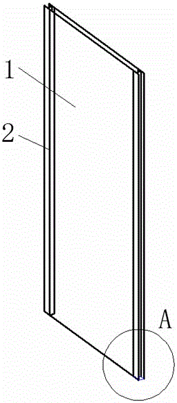
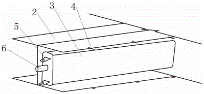
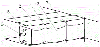
[0022] A method of using an interface box, comprising the following steps: (1) Processing of the airbag 3: the section of the airbag 3 is processed according to the size of the interface groove 2, the length of the airbag 3 is according to the length of the ground connection wall, and the upper end of the airbag 3 is welded and pumped Lifting handle 5, the cross-sectional size of the airbag 3 is slightly larger than the size of the interface groove 2, and the length of the airbag 3 is 1 meter longer than the ground connection wall; (2), steel bar processing: bind the steel bar according to the drawing of the ground connection wall to form the Reinforcement cage 1, weld the interface groove 2 on both sides of the reinforcement cage 1, and weld buckle fixing ribs 4 on the outside of the interface groove 2 according to the interval of 1.5 meters; (3), installation of airbag 3: for the inflated airbag 3. Place the upper end of the interface slot 2 in the interface slot 2, start to ...

Embodiment 2

[0024] A method of using an interface box, comprising the following steps: (1) Processing of the airbag 3: the section of the airbag 3 is processed according to the size of the interface groove 2, the length of the airbag 3 is according to the length of the ground connection wall, and the upper end of the airbag 3 is welded and pumped Pull out the handle 5, the section size of the airbag 3 is slightly larger than the size of the interface groove 2, and the length of the airbag 3 is 2 meters longer than the ground connection wall; (2), steel bar processing: bind the steel bar according to the drawing of the ground connection wall to form the Reinforcement cage 1, weld the interface groove 2 on both sides of the reinforcement cage 1, and weld buckle fixing ribs 4 on the outside of the interface groove 2 according to the distance of 2 meters; (3), installation of airbag 3: for the inflated airbag 3. Place the upper end of the interface slot 2 in the interface slot 2, start to infl...

Embodiment 3

[0026] A method of using an interface box, comprising the following steps: (1) Processing of the airbag 3: the section of the airbag 3 is processed according to the size of the interface groove 2, the length of the airbag 3 is according to the length of the ground connection wall, and the upper end of the airbag 3 is welded and pumped Lifting handle 5, the cross-sectional size of the airbag 3 is slightly larger than the size of the interface groove 2, and the length of the airbag 3 is 1 meter longer than the ground connection wall; (2), steel bar processing: bind the steel bar according to the drawing of the ground connection wall to form the Reinforcement cage 1, weld the interface groove 2 on both sides of the reinforcement cage 1, and weld buckle fixing ribs 4 on the outside of the interface groove 2 according to the distance of 2 meters; (3), installation of airbag 3: for the inflated airbag 3. Place the upper end of the interface slot 2 in the interface slot 2, start to in...


PUM


Abstract

The invention discloses an underground diaphragm wall air bag type interface box and a use method thereof. The underground diaphragm wall air bag type interface box comprises an air bag, a reinforcement cage and fixing buckles, wherein interface grooves are formed in the two sides of the reinforcement cage; multiple buckle fixing ribs are arranged on the outer sides of the interface grooves; the air bag is located inside the interface grooves; the section of the air bag is rectangular; a charging connector is arranged at the upper end of the air bag; pulling-out lifting handles are arranged on the two sides of the charging connector; the fixing buckles are located inside the buckle fixing ribs; and the air bag and the fixing buckles are fixed to one another in a mutual squeezing mode. The use method comprises the first step of machining of the air bag, the second step of machining of reinforcing steel bars, the third step of installation of the air bag, the fourth step of sinking of the reinforcement cage and pouring of concrete, and the fifth step of pulling out of the air bag.

Description

technical field [0001] The invention relates to the field of civil engineering construction, in particular to a method for using an airbag type interface box machine for an underground continuous wall. Background technique [0002] In the field of civil engineering construction, especially in the field of subway and building construction, the construction of underground diaphragm walls is often carried out. The underground diaphragm walls are constructed in sections, with interface grooves set between the two sections, and the end of one section is "concave". The adjacent panels are embedded in the "concave"-shaped interface in a "convex" shape to form a mutual fitting to ensure the integrity and water-tightness of the entire underground continuous wall. However, if the "concave"-shaped interface is not filled and closed, concrete will often flow in when pouring concrete, which will seriously affect the tightness of the interface and cause water leakage from the ground to th...

Claims


Application Information

Patent Timeline
Patent Type & Authority Applications(China)
IPC IPC(8): E02D5/18E02D5/20
CPCE02D5/185E02D5/20
Inventor 程永志刘建强
Owner THE THIRD ENG CO LTD OF CCCC SECOND HIGHWAY ENG BUREAU
Why Eureka
Try Eureka