Mobile charging pile and application method thereof

A technology of mobile charging piles and charging piles, applied in charging stations for charging mobile devices, charging management of batteries, collectors, etc., can solve problems such as high pressure on the power grid, difficulty in installation and transformation, and low coverage rate, and reduce the pressure on the power grid , the effect of making an appointment convenient

Pending Publication Date: 2016-06-22
赵紫州
View PDF0 Cites 40 Cited by
  • Summary
  • Abstract
  • Description
  • Claims
  • Application Information

AI Technical Summary

Problems solved by technology

At present, the commonly used charging facilities are mainly large charging stations, outdoor charging piles, community charging piles, and p...

Method used


Image

  • Mobile charging pile and application method thereof
  • Mobile charging pile and application method thereof

Examples


Embodiment 1

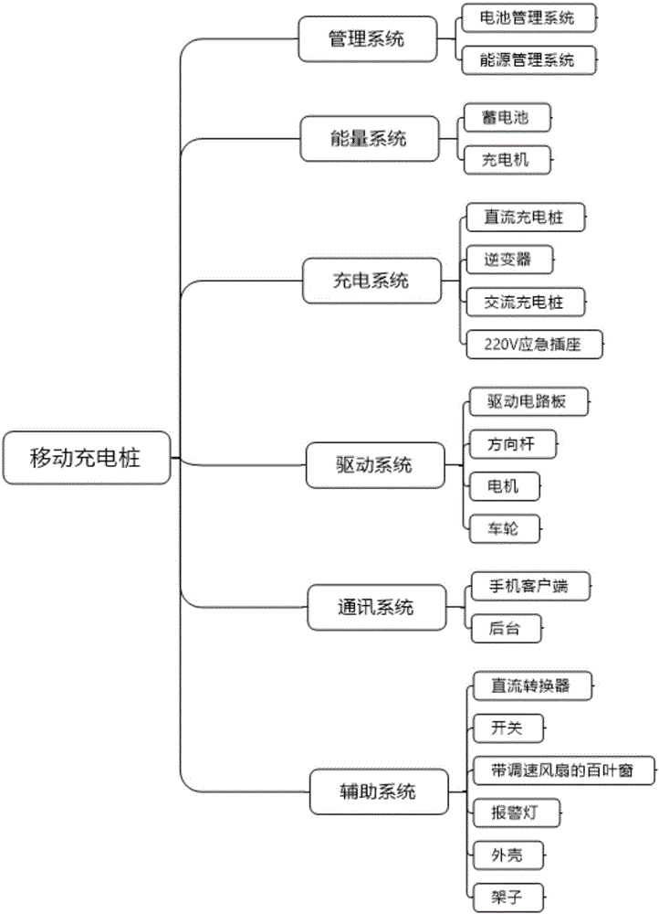
[0031] figure 1It is a schematic structural diagram of a mobile charging pile system provided by an embodiment of the present invention. Such as figure 1 As shown, the mobile charging pile includes: a management system, a charging system, an energy system, a driving system, a communication system and an auxiliary system. Among them, the management system includes the battery management system and the energy management system, which is responsible for integrating and controlling other systems; the energy system includes batteries and chargers, which are used to store and provide electric energy for other systems; the charging system includes DC charging piles, inverters, AC Charging piles and 220V emergency sockets are responsible for converting electric energy and charging electric vehicles; the drive system includes drive circuit boards, motors, steering rods, and wheels to control the movement of charging piles; the communication system includes mobile phone clients and bac...

Embodiment 2

[0049] figure 1 It is a schematic structural diagram of a mobile charging pile system provided by an embodiment of the present invention. Such as figure 1 As shown, the mobile charging pile includes: a management system, a charging system, an energy system, a driving system, a communication system and an auxiliary system. Among them, the management system includes the battery management system and the energy management system, which is responsible for integrating and controlling other systems; the energy system includes batteries and chargers, which are used to store and provide electric energy for other systems; the charging system includes DC charging piles, inverters, AC Charging piles and 220V emergency sockets are responsible for converting electric energy and charging electric vehicles; the drive system includes drive circuit boards, motors, steering rods, and wheels to control the movement of charging piles; the communication system includes mobile phone clients and ba...


PUM


Abstract

The invention relates to a mobile charging pile and its usage method. The mobile charging pile includes: a management system, a charging system, an energy system, a driving system, a communication system and an auxiliary system. Among them, the management system includes the battery management system and the energy management system, which is responsible for integrating and controlling other systems; the energy system includes batteries and chargers, which are used to store and provide electric energy for other systems; the charging system includes DC charging piles, inverters, AC Charging piles and 220V emergency sockets are responsible for converting electric energy and charging electric vehicles; the drive system includes drive circuit boards, motors, steering rods, and wheels to control the movement of charging piles; the communication system includes mobile phone clients and backgrounds, responsible for contacting car owners , mobile charging pile and its person in charge; auxiliary systems include DC converters, switches, shutters, warning lights, shelves and housings, which are used to assist the operation of other systems. The invention has the advantages of convenient reservation, flexible maneuvering and unlimited charging positions.

Description

technical field [0001] The invention relates to the field of mobile charging pile design, in particular to a mobile charging pile and a method for using the same. Background technique [0002] With the advent of the new energy tide, electric vehicles have become a hot new force, but with the increase in the penetration rate of electric vehicles, various restrictive factors have also been exposed, one of which is the charging problem. Compared with traditional fuel vehicles, electric vehicles have a shorter cruising range, so the requirements for the penetration rate and coverage of charging facilities are relatively high. At present, the commonly used charging facilities are mainly large charging stations, outdoor charging piles, community charging piles, and public parking lot charging piles. Shortcomings such as long queuing time make it difficult to meet the growing charging demand of electric vehicles. Contents of the invention [0003] The invention aims to overcome...

Claims


Application Information

Patent Timeline
IPC IPC(8): H02J7/00H02J7/34H02J3/32
CPCH02J7/0022H02J7/0027H02J3/32H02J7/34
Inventor 赵紫州梁鸿宇邱晨
Owner 赵紫州
Why Eureka
Try Eureka