Motor

A rotor and stator technology, applied in the field of motors, can solve the problems of Hall chip installation and positioning troubles, increase the difficulty of iron core manufacturing, Hall chips cannot be installed compactly, etc., and achieve a more compact and reasonable motor structure.

Active Publication Date: 2016-06-22
苏州同盛电器有限公司
View PDF5 Cites 1 Cited by
  • Summary
  • Abstract
  • Description
  • Claims
  • Application Information

AI Technical Summary

Problems solved by technology

[0003] However, for the motor with the above-mentioned structure, since the Hall chip is embedded and installed inside the stator core, the Hall chip is embedded in the wire slot or on the iron core. If it is embedded on the iron core, it must be placed on the The surface of the iron core is grooved. This structure not only increases the difficulty of manufacturing the iron core, but also the installation and positioning of the Hall chip is extremely troublesome. The Hall chip cannot be compactly installed on a component, and the production process of the product is very poor.

Method used


Image

  • Motor
  • Motor
  • Motor

Examples


Embodiment Construction

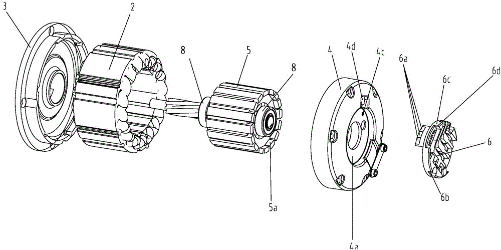
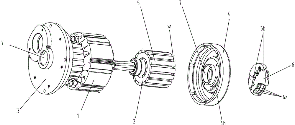
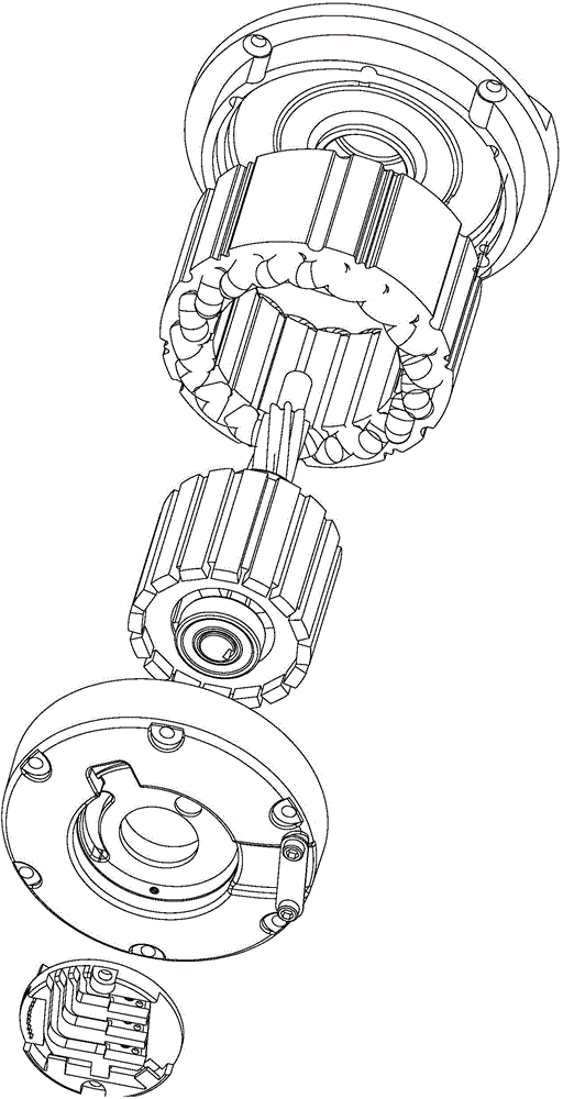
[0020] Figure 1 ~ Figure 3 A specific embodiment of the motor of the present invention is shown. The motor is an inner-rotor-outer-stator motor, which includes a rotor 1, a stator 2 sleeved outside the rotor, and is arranged on the front side of the stator and is opposite to the stator. A fixed front cover 3, and a rear cover 4 which is arranged on the rear side of the stator and is relatively fixed to the stator, and the periphery of the rotor 1 is fixed with a plurality of rare earth magnets 5 which are evenly spaced in a circular shape. The rare earth magnets 5 are strip-shaped and arranged parallel to the axial direction of the rotor 1 . The number of rare earth magnets 5 described in this example is 16 in total.

[0021] The key improvement of this embodiment is: in this example, the rear end of each rare earth magnet 5 has been lengthened so that the rear end of each rare earth magnet 5 extends backward by a certain length and protrudes beyond the rotor 1. The rear en...


PUM


Abstract

The present invention discloses a motor comprising a rotor, a stator which sleeves the rotor, a front cover which is arranged at the front side of the stator and is relatively fixed to the stator, and a back cover which is arranged at the back side of the stator and is relatively fixed to the stator. A plurality of rare earth magnets in annular uniform spaced distribution is fixed at the periphery of the rotor. The rare earth magnets are stripe structures and are parallel to the axis direction of the rotor. The back end of each of the rare earth magnets is raised from the back end surface of the rotor, and thus a magnet steel extending part projecting from the back end face of the rotor is formed. The back end of the back cover is provided with a receiving groove, and the bottom of the receiving groove is provided with an arc-shaped long hole. A Hall sensor is fixedly installed in the receiving groove and has three Hall chips in arc-shaped uniform space distribution. The Hall chips go through the arc-shaped long hole and are at the inner side of the magnet steel extending part. Compared with a motor with a traditional structure, the motor of the invention has the advantages of compact structure and easy production.

Description

technical field [0001] The invention relates to an electric machine. Background technique [0002] The inner rotor outer stator type motor generally includes a rotor, a stator sleeved outside the rotor, a front cover arranged on the front side of the stator and relatively fixed to the stator, and a rear cover arranged on the rear side of the stator and relatively fixed to the stator. The periphery of the rotor is fixed with a plurality of rare-earth magnets evenly spaced in a circular shape, and it also includes 3 Hall chips embedded in the inner side of the stator core. The distance between the Hall chip and the outer surface of the rare-earth magnets on the rotor Very close, so that the Hall chip can sense the angle between the rare earth magnet and the Hall chip, so as to know the position of the rotor. [0003] However, for the motor with the above-mentioned structure, since the Hall chip is embedded and installed inside the stator core, the Hall chip is embedded in the...

Claims


Application Information

Patent Timeline
Patent Type & Authority Applications(China)
IPC IPC(8): H02K11/00
Inventor 马庆一
Owner 苏州同盛电器有限公司
Why Eureka
Try Eureka