
Motor Punching Stacking Device

A motor punching and column technology, which is applied to the field of motor punching stacking devices, can solve the problems of increasing production cost, the position of riveting holes or welding holes is disordered, affecting production efficiency, etc., and achieves the effect of improving production efficiency.

Active Publication Date: 2018-05-22
FLYING ELECTRIC CO LTD IN ANHUI
View PDF4 Cites 0 Cited by
  • Summary
  • Abstract
  • Description
  • Claims
  • Application Information

AI Technical Summary

Problems solved by technology

[0002] The iron core of the motor is generally made of stacked punches. The punches are stamped and formed separately, and then the multi-layer punches are riveted or welded into one body. During the stacking process, it is necessary to ensure that the riveting holes or welding holes of each layer of punches are correct. Yes, but because each piece of motor punching is formed separately, the positions of the riveting holes or welding holes of each punching piece are scattered and disorderly, which requires manual stacking of the punching pieces. The production process is time-consuming and laborious, which seriously affects Production efficiency, increased production costs

Method used


Image

  • Motor Punching Stacking Device
  • Motor Punching Stacking Device

Examples


Embodiment Construction

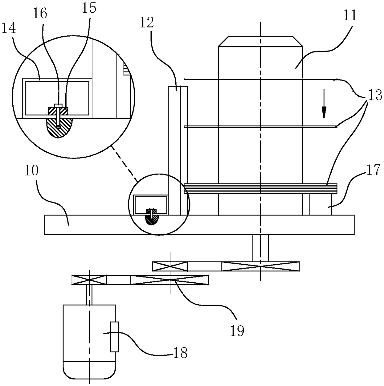
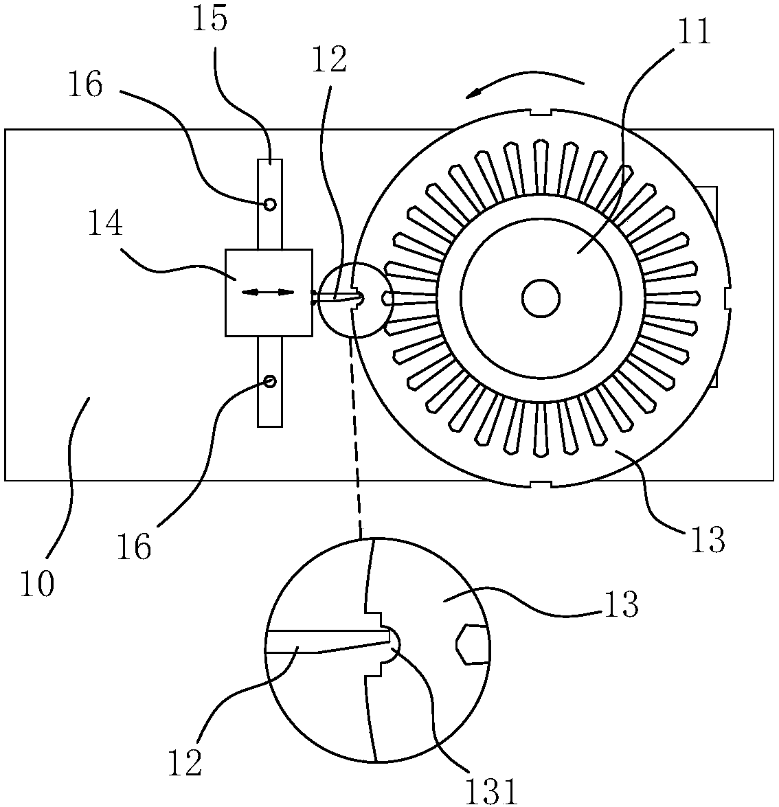
[0015] like figure 1 , 2 As shown, a motor punching stacking device includes a column 11 and a blocking piece 12 arranged on the base 10, the column 11 is rotatably arranged, and the blocking piece 12 is elongated and vertically arranged beside the column 11. The height of the top of the sheet 12 is lower than the height of the top of the column 11; when the motor punch 13 is sleeved on the column 11, the friction between the column 11 and the motor punch 13 can make the motor punch 13 rotate with the column 11, and the motor The punching piece 13 can fall by its own gravity; the distance from the blocking piece 12 to the center of the column 11 is smaller than the outer diameter of the motor punching piece 13, and the motor punching piece 13 will stop falling when it falls to the top of the blocking piece 12; the motor punching piece There is a gap 131 on the upper edge of 13. When the gap 131 is rotated to be opposite to the blocking piece 12, the motor punching piece 13 ca...


PUM


Abstract

The invention belongs to the field of the production and manufacturing process of motor punching sheets, and particularly relates to a stacking device for motor punching sheets. The device comprises an upright column and a blocking piece both arranged on a base. The upright column is rotatably arranged. The blocking piece is strip-shaped and is vertically arranged next to the upright column. The height of the top end of the blocking piece is lower than the height of the top end of the upright column. When a motor punching sheet is sleeved onto the upright column, the friction force between the upright column and the motor punching sheet drives the motor punching sheet to rotate along with the upright column. At the same time, the motor punching sheet can fall down under the effect of the gravity itself. The distance between the blocking piece and the center of the upright column is smaller than the outer diameter of the motor punching sheet. When the motor punching sheet falls onto the top end of the blocking piece, the motor punching sheet stops falling. The upper edge of the motor punching sheet is provided with a notch. When the notch is rotated to be right facing the blocking piece, the motor punching sheet is kept away from the blocking piece to continuously fall down. Meanwhile, under the limiting effect of the blocking piece, the motor punching sheet stops rotating. According to the technical scheme of the invention, the upright column drives the motor punching sheet to rotate. Meanwhile, the limiting effect is realized by the blocking piece, so that the motor punching sheet is automatically aligned. Therefore, multiple layers of motor punching sheets are automatically stacked in order, so that the production efficiency is improved.

Description

technical field [0001] The invention belongs to the field of motor punching production and manufacturing, and particularly relates to a motor punching stacking device. Background technique [0002] The iron core of the motor is generally formed by stacking punching pieces. The punching pieces are individually punched and formed, and then the multi-layer punching pieces are riveted or welded together. During the stacking process, it is necessary to ensure that the riveting holes or welding holes of each layer of punching pieces are correct. Yes, but since each motor punching piece is formed separately, the positions of the riveting holes or welding holes of each punching piece are scattered and disordered, which requires manual ordering of the punching pieces, which is time-consuming and labor-intensive in the production process, seriously affecting Production efficiency and increased production costs. SUMMARY OF THE INVENTION [0003] The purpose of the present invention ...

Claims


Application Information

Patent Timeline
Patent Type & Authority Patents(China)
IPC IPC(8): H02K15/02
CPCH02K15/02
Inventor 金爱民王锦波金超
Owner FLYING ELECTRIC CO LTD IN ANHUI
Learn More