Wireless network buoy system used for environment monitoring

A wireless network and environmental monitoring technology, applied in the direction of buoys, transmission systems, special-purpose ships, etc., can solve problems such as the inability to realize real-time information interaction, the antenna cabin is easy to be found, and the satellite transmission delay is large, so as to improve the data transmission rate and data accuracy, flexible power supply, and flexible collection effects

Inactive Publication Date: 2016-06-22
彭郑 +3
View PDF8 Cites 10 Cited by
  • Summary
  • Abstract
  • Description
  • Claims
  • Application Information

AI Technical Summary

Problems solved by technology

The disadvantage of this transmission system and method is that it is bulky, the antenna cabin is easy to be found, and the satellite transmission delay is too large to realize real-time information interaction

Method used


Image

  • Wireless network buoy system used for environment monitoring
  • Wireless network buoy system used for environment monitoring
  • Wireless network buoy system used for environment monitoring

Examples


Embodiment 1

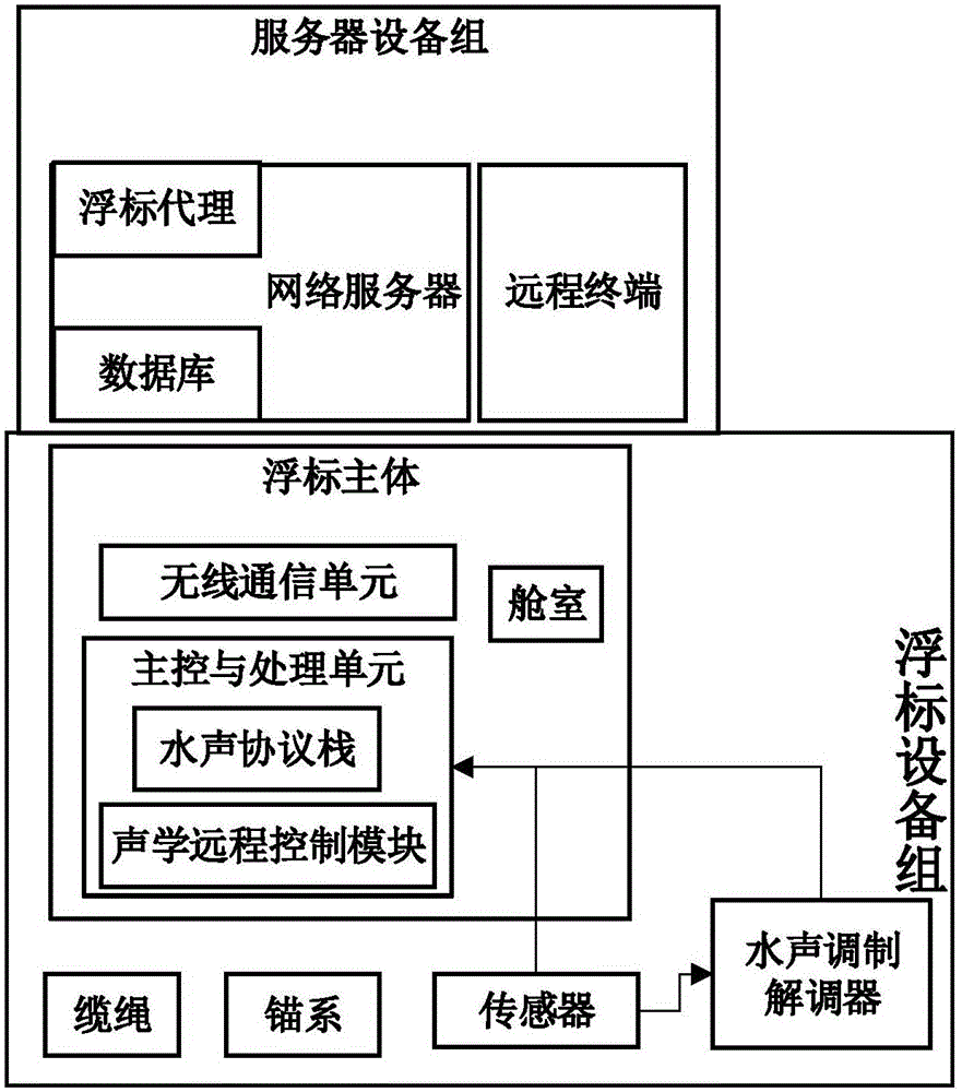
[0041] figure 1 It is a wireless network buoy system for environmental monitoring, and its composition is as follows: figure 1 as shown, figure 2 It is a composition and connection relationship diagram of buoy device groups in a wireless network buoy system for environmental monitoring in this embodiment.

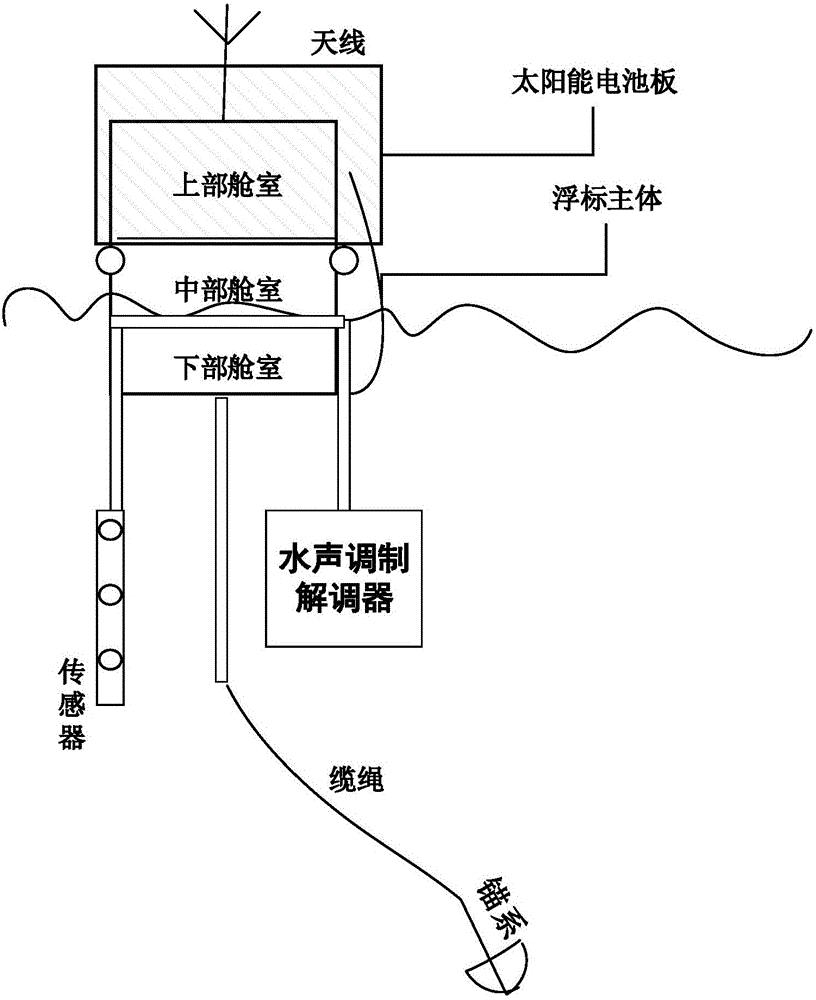
[0042] This example figure 2The middle sensor is the sensor module, in this embodiment, it is a CTD sensor, which is used to measure water temperature, salinity and depth; the underwater acoustic modem and the underwater acoustic MODEM; the main body of the buoy includes the lower cabin, the middle cabin and the upper cabin, wherein the battery is located in the lower cabin ; The middle compartment contains the main control and processor unit; the upper compartment is equipped with a wireless communication unit, wherein the antenna is an LTE antenna, which is installed on the external bracket of the upper compartment to ensure good wireless signal quality.

[0043] S...

Embodiment 2

[0064] This embodiment is based on a method for transmitting software configuration in a wireless network buoy system for environmental monitoring according to the present invention, which is embodied in the main control and processing unit in the buoy device group.

[0065] The main control and processing unit of this embodiment is equipped with ARM core CPU, large-capacity RAM (64MB in this embodiment) and flash memory (16MB in this embodiment), and runs on high main frequency (main frequency is 400MHz in this embodiment ); the main control and processing unit is also equipped with an SD memory card (32GB in this embodiment) for storing log files and program data.

[0066] There are three RS232 interfaces on the main control and processing unit in this embodiment, which are respectively used to connect the wireless communication unit, the underwater acoustic modem and the CTD sensor.

[0067] The main control and processing unit is located in figure 2 In the circuit board ...


PUM


Abstract

The present invention relates to a wireless network buoy system used for environment monitoring. The wireless network buoy system used for environment monitoring comprises a server equipment set and a buoy equipment set, the server equipment set comprises a network server and a remote terminal, and the network server comprises a database and a buoy agent. The buoy equipment set mainly contains a buoy main body, and the buoy main body comprises a cabin, a power supply module, a wireless communication unit, a main control and processor unit, an underwater sound modulator-demodulator and a sensor. The main control and processor unit comprises an underwater sound protocol stack and an acoustics remote control module, the underwater sound protocol stack especially contains a transparent layer and can support the cross-layer design, and the acoustics remote control module is allowed by the remote terminal to start and stop nodes and modify a communication protocol stack. The underwater sound modulator-demodulator adopts a multi-carrier and adaptive modulation coding technology, and the sensor can be connected with the main control and processor unit or the underwater sound modulator-demodulator. The wireless network buoy system used for environment monitoring of the present invention realizes the flexible and friendly interface and high communication transmission efficiency, and enables the performances of a conventional environment monitoring buoy system to be improved effectively.

Description

technical field [0001] The application relates to a wireless network buoy system for environmental monitoring, which is used in the technical field of water surface and underwater environmental monitoring of various water bodies. Background technique [0002] Most of the traditional sea surface or underwater environment monitoring is in the form of wired cables. In recent years, network nodes based on GPRS / TDMA and other types have appeared. However, their transmission rate and real-time information transmission are the bottlenecks in the development of various water surface monitoring technologies. [0003] After searching, domestic and foreign patents and documents related to wireless network buoy equipment involve satellite communication information transmission, wireless network information transmission, wireless local area platform information interaction, etc. The relevant literature is as follows: [0004] 1) Utility model patent "A remote monitoring system for chann...

Claims


Application Information

Patent Timeline
IPC IPC(8): H04L29/08
CPCB63B22/00H04L67/025H04L67/06H04L67/12
Inventor 彭郑马晓莉韩贵韬
Owner 彭郑
Why Eureka
Try Eureka