
Multi-working box sand mould 3D printing equipment

A 3D printing and work box technology, applied in the field of 3D printing, can solve the problems of limited adjustable space, inability to meet production needs, and no simultaneous sand laying and printing of multiple work boxes, so as to reduce the cost of sand molding and improve printing efficiency. Effect

Active Publication Date: 2016-06-29
NINGXIA KOCEL MOLD
View PDF5 Cites 69 Cited by
  • Summary
  • Abstract
  • Description
  • Claims
  • Application Information

AI Technical Summary

Problems solved by technology

However, due to the limited space for adjusting the equipment size and operating speed, the effect of using the above method to improve printing efficiency is not ideal, and it still cannot meet the production needs. The rapid development of the sand mold 3D printing application field urgently requires a solution that can double the printing efficiency. feasible solution
Although in the prior art, the patent document with the notification number CN203887169U discloses a 3D printing production line, and at least two working boxes are designed to improve printing efficiency, but this technology is the applicant's early research results, and the essence of the structure is Two or more work boxes take turns to print. When one work box completes the printing job, another empty work box can quickly come to fill the vacancy and continue printing. Therefore, only one work box can print at the same time, and Simultaneous sanding and printing of multiple working boxes are not realized. Moreover, the existing technology has shortcomings in the printing head, sanding device and driving device, and cannot realize the demand of simultaneous printing.

Method used


Image

  • Multi-working box sand mould 3D printing equipment
  • Multi-working box sand mould 3D printing equipment
  • Multi-working box sand mould 3D printing equipment

Examples


Embodiment Construction

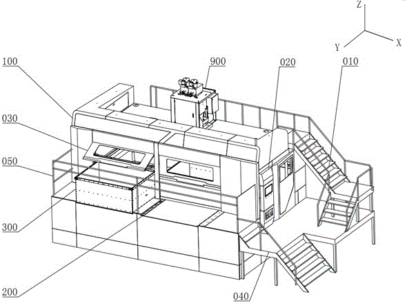
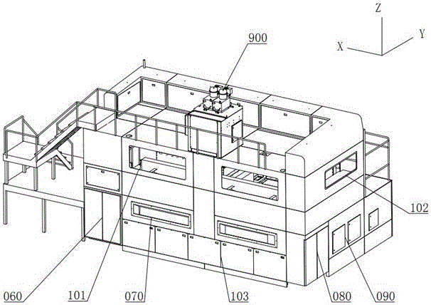
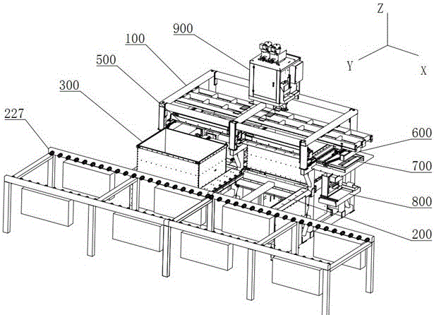
[0049] In order to enable those skilled in the art to better understand the technical solutions of the present invention, the present invention will be further described in detail below in conjunction with specific examples.

[0050] Overall structure of the present invention is as Figure 1-4 As shown, the multi-box sand mold 3D printing equipment includes: main frame (100), work box conveying system (200), work box (300), work box lifting mechanism (400), sand spreader (500), printing head (600), cleaning device (700), liquid material system (800), sand mixing device (900) and electrical system, wherein the main frame (100) includes at least three columns, and the main frame (100) composed of more than three columns ) After the assembly is completed, more than two independent work areas are formed, and a set of work box jacking mechanisms (400) are respectively installed at the bottom of each work area. A work box conveying system (200) is arranged above the two or more ind...


PUM


Abstract

The invention relates to multi-working box sand mould 3D printing equipment. The multi-working box sand mould 3D printing equipment comprises a main body framework (100), a working box conveying systems (200), working boxes (300), working box jacking mechanisms (400), sand laying devices (500), a printing head (600), a cleaning device (700), a liquid material system (800), a sand mixing device (900) and an electric system. The multi-working box sand mould 3D printing equipment provided by the invention comprises two or more working boxes which are combined with sand mixing pots, the synchronous operation sand laying devices, the penetration-type printing head, the working box synchronous jacking mechanisms and the electric system which are matched with the working boxes; the two or more working boxes work simultaneously during sand laying and printing operation; and compared with single-working box sand mould 3D printing equipment with the same specification, the multi-working box sand mould 3D printing equipment has the advantages that in the same time period, the printing efficiency can be improved by times, so that the cost of sand moulds can be effectively lowered, and production requirements can be met more rapidly.

Description

technical field [0001] The invention belongs to the field of 3D printing, is mainly used in the field of 3D printing of sand molds for casting, and specifically relates to a multi-box sand mold 3D printing device which has multiple working boxes and can print simultaneously. Background technique [0002] At present, sand mold 3D printing equipment generally has problems such as low printing efficiency, high time cost, and failure to meet production needs. The main reason is that the structure of the sand printing equipment is similar. They are all composed of a single work box, sand spreader, print head and other functional modules, and the working order and required time of each functional module are basically fixed. If it is necessary to improve the single work box form The printing efficiency of sand printing equipment can only be achieved by increasing the size and increasing the running speed. However, due to the limited space for adjusting the equipment size and opera...

Claims


Application Information

Patent Timeline
Patent Type & Authority Applications(China)
IPC IPC(8): B22C9/02B33Y30/00
CPCB33Y30/00B22C9/02B22C9/00B22C11/00B29C67/00Y02P10/25B29C64/20
Inventor 彭凡刘轶周志军徐云龙杜文军马强赵龙马睿
Owner NINGXIA KOCEL MOLD
Learn More