Electromagnetic energy harvesting system based on passive suspension

A passive suspension and energy harvesting technology, applied in the direction of suspension, elastic suspension, electromechanical devices, etc., can solve the problems of increased distance between the car chassis and the road, complex structure, poor reliability, etc., and achieve good vibration reduction effect , good application prospects, wide range of effects

Inactive Publication Date: 2016-06-29
DALIAN UNIV OF TECH
View PDF6 Cites 18 Cited by
  • Summary
  • Abstract
  • Description
  • Claims
  • Application Information

AI Technical Summary

Problems solved by technology

[0003] However, these energy-feeding suspensions have the following disadvantages, including: 1) this type of suspension is generally an active suspension, which needs to provide energy to attenuate the vibration of the car while capturing energy, and often "makes ends meet"; 2) due to energy-feeding The output voltage of the type suspension will not be too high. In order to avoid the dead zone of the motor, a booster circuit is usually added to ensure the normal vibration reduction function of the suspension. The structure is complex; 3) The working state of the motor needs to be controlled by a corresponding control system , which leads to high manufacturing cost and poor reliability of the suspension; 4) The layout space of the suspension is limited, and the increased motor makes the layout of the suspension system difficult. At the same time, it may increase the distance between the chassis and the road, reducing the handling stability

Method used


Image

  • Electromagnetic energy harvesting system based on passive suspension
  • Electromagnetic energy harvesting system based on passive suspension
  • Electromagnetic energy harvesting system based on passive suspension

Examples


Embodiment Construction

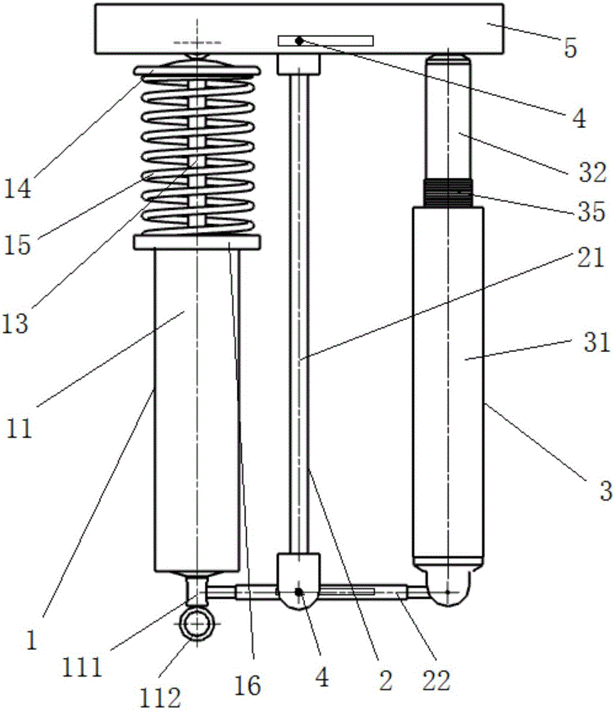
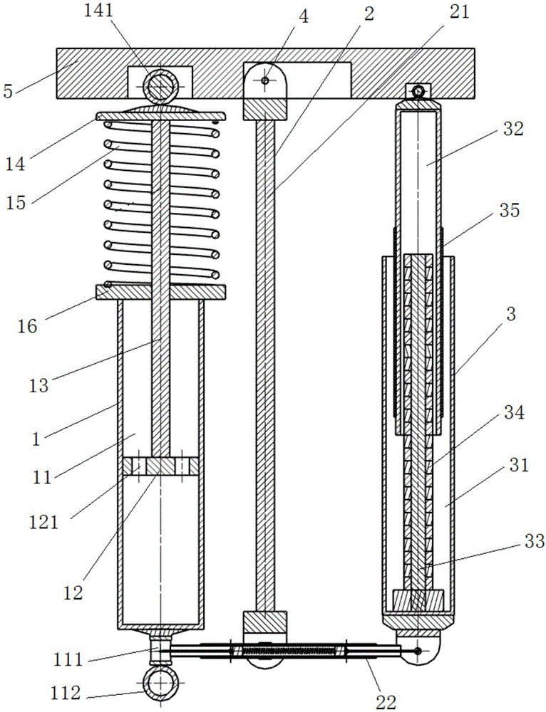
[0028] Such as Figure 1-Figure 8 As shown, an electromagnetic energy harvesting system based on passive suspension includes a hydraulic shock absorber 1 arranged in parallel, a speed amplification mechanism 2 and an electromagnetic energy harvesting mechanism 3, and the speed amplification mechanism 2 is located in the hydraulic shock absorber 1 and between the electromagnetic energy harvesting mechanism 3,

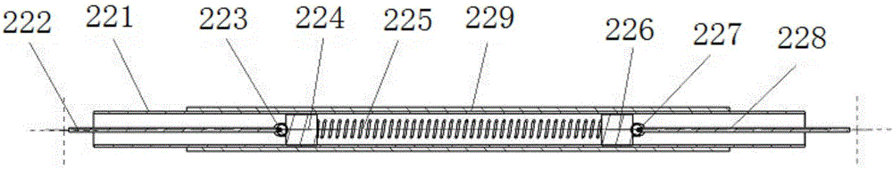
[0029] The speed amplifying mechanism 2 includes support rods 21 parallel to the hydraulic shock absorber 1 and the electromagnetic energy harvesting mechanism 3 respectively, the lower end of the support rods 21 is provided with a speed transmission mechanism 22, and the speed transmission mechanism 22 It includes a guide sleeve 221 and a connecting rod I222, a ball link I223, a slider I224, a spring I225, a slider II226, a ball link II227, and a connecting rod II228 connected sequentially within the guide sleeve 221. The connecting rod I222 The other end is connected ...


PUM


Abstract

The invention discloses an electromagnetic energy harvesting system based on a passive suspension. The electromagnetic energy harvesting system consists of a hydraulic absorber, a speed amplifying mechanism and an electromagnetic energy harvesting mechanism. The speed amplifying mechanism is disposed between the hydraulic absorber and the electromagnetic energy harvesting mechanism and used for amplifying a vibration speed of a suspension. The vibration energy of the suspension is converted into electric energy to be stored. When a car runs on an uneven pavement, the vibration of the pavement is transferred to a car suspension by virtue of a tire to cause the up-down vibration of a car hydraulic absorber, and the vibration speed of the suspension is transferred to the electromagnetic energy harvesting mechanism by virtue of the speed amplifying mechanism, so that an intermediate rod of the electromagnetic energy harvesting mechanism and an inner drum make relative movement, an induction electromotive force is generated according to an electromagnetic induction principle, and the induction electromotive force is finally stored. Meanwhile, due to the existence of an Ampere force, the vibration absorption effect of the system is further improved. By adopting the structure, a complicated feedback system, a control system and additional power elements are not needed, so that the electromagnetic energy harvesting system is simple in structure, low in cost, wide in application range and relatively good in application prospect.

Description

technical field [0001] The invention belongs to the field of energy harvesting of automobile suspensions, in particular to an electromagnetic energy harvesting system based on passive suspensions. Background technique [0002] The research on the energy dissipation of vehicle shock absorbers shows that the recovery of suspension vibration energy has important practical significance for realizing energy saving of vehicles. Therefore, the structural design of the suspension is particularly critical, which directly affects the vibration reduction performance and energy recovery efficiency. In recent years, a variety of energy-feeding suspension structures have appeared. For example, domestic patent 200410013577 proposes a linear motor-based energy-feeding suspension system. The suspension system fixedly connects the mover of the linear motor to the spring of the vehicle. At the upper mass, the stator of the linear motor is fixedly connected to the unsprung mass of the vehicle....

Claims


Application Information

Patent Timeline
Patent Type & Authority Applications(China)
IPC IPC(8): B60G13/14H02K35/02
CPCB60G13/14H02K35/02
Inventor 高仁璟石文武赵剑李明丽刘书田
Owner DALIAN UNIV OF TECH
Why Eureka
Try Eureka