Forced circulation ionic membrane electrolytic bath

An ionic membrane electrolytic cell and forced circulation technology, applied in the field of electrolytic cells, can solve the problems of affecting economic benefits, low current density, low conversion rate, etc.

Active Publication Date: 2016-06-29
梧州市联溢化工有限公司
View PDF5 Cites 3 Cited by
  • Summary
  • Abstract
  • Description
  • Claims
  • Application Information

AI Technical Summary

Problems solved by technology

Due to the limited area of ​​the fluid flowing through the electrode network and membrane surface and the low current density of the traditional forced circulation mode electrolyzer, the output of the product is not large when the conversion rate is not high, which seriously affects the economic benefits

Method used


Image

  • Forced circulation ionic membrane electrolytic bath
  • Forced circulation ionic membrane electrolytic bath
  • Forced circulation ionic membrane electrolytic bath

Examples


Embodiment Construction

[0020] The present invention will be described in detail below in conjunction with examples.

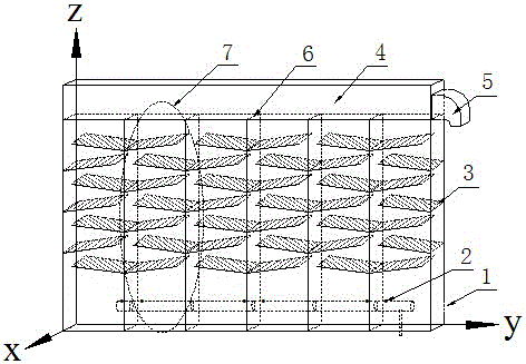
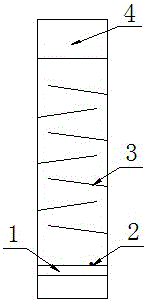
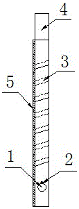
[0021] The main structure of the ion membrane electrolyzer of the present invention includes an inlet pipe, an anode frame chamber, a baffle plate, a gas-liquid separation chamber and an outlet pipe. The anode frame chamber is a frame structure, and several grids are arranged on the frame structure to divide the frame structure into several unit chambers. The baffles are baffles embedded on the grid according to a certain inclination angle and according to certain rules, and the baffles are arranged staggered left and right on the grids on both sides of the unit room. Electrolyte inlet pipes are distributed into each cell chamber. The top of each unit is connected to the gas-liquid separation chamber, and the two-phase mixture is collected in the top gas-liquid separation chamber and flows out from the outlet pipe on the side of the gas-liquid separation chamber.

[0022] figure 1...


PUM

PropertyMeasurementUnit
heightaaaaaaaaaa

Abstract

The invention discloses a forced circulation ionic membrane electrolytic bath, and relates to electrolytic baths. The anode ionic membrane electrolytic bath internally comprises an inlet pipe, an anode frame chamber, a gas-liquid separation chamber and an outlet; the anode frame chamber is of a frame structure, a plurality of gratings are arranged on the frame structure, and divide the anode frame chamber into a plurality of unit chambers, a plurality of baffle plates are distributed in each unit chamber, and the baffle plates are distributed on the gratings at the two ends of the unit chambers in a left-and-right staggered manner; and due to the fact that the thickness of the ionic membrane electrolytic bath is small, when the ionic membrane electrolytic bath is applied to the chlor-alkali technology process, electrolytic process of the high current density can be achieved, and therefore the yield is increased; secondly, due to the baffle effect of the baffle plates, the height of the ionic membrane electrolytic bath can be reduced to 1/2 to 3/4 of the height of a traditional ionic membrane electrolytic bath, and the manufacturing cost of the electrolytic bath can be greatly saved; and finally the baffle plates which incline by a certain angle enable electrolytes flowing through the baffle plates to rotate in an orientation manner, the radial mixing degree is increased, and the raw material using rate is better improved.

Description

technical field [0001] The invention relates to an electrolytic cell, in particular to a forced circulation ion membrane electrolytic cell. Background technique [0002] Compared with the traditional mercury method or diaphragm method, the ionic membrane soda method has many advantages, such as low total energy consumption, no mercury or asbestos polluting the environment, and easy operation and control. Today's newly built chlor-alkali production facilities generally use the ion-exchange membrane method to make alkali, and some of the existing mercury-based or diaphragm-based chlor-alkali plants are also transformed into ion-exchange membrane methods while undergoing technological transformation. [0003] The ionic membrane electrolyzer uses a cation exchange membrane to separate the electrolytic cell into two parts, the anode frame chamber and the cathode frame chamber. Through the selective permeability of the cation membrane, the cation membrane allows positively charged...

Claims


Application Information

Patent Timeline
Patent Type & Authority Applications(China)
IPC IPC(8): C25B9/00
CPCC25B9/00
Inventor 张丽成蕾刘国桢王伟红刘云义
Owner 梧州市联溢化工有限公司
Why Eureka
Try Eureka