
Prediction method for flowing bottomhole pressure of gas well

A technology of bottomhole flow pressure and prediction method, which is applied in wellbore/well components, measurement, earthwork drilling and production, etc. It can solve the problem of gas well production, casing pressure and bottomhole flow pressure changes, the difficulty of gas well bottomhole flow pressure prediction, and the time-consuming actual measurement And other issues

Inactive Publication Date: 2016-06-29
SHANGHAI UNIV
View PDF5 Cites 8 Cited by
  • Summary
  • Abstract
  • Description
  • Claims
  • Application Information

AI Technical Summary

Problems solved by technology

Usually, in the initial stage of gas field production, in order to obtain the dynamic parameters of the formation and deepen the understanding of the reservoir, a small number of gas wells will be installed with downhole pressure gauges to measure the bottom hole flow pressure. However, due to the time-consuming measurement, high cost and safety risks Therefore, the bottomhole flowing pressure of most other wells needs to be calculated by using the model
Many of these calculation models are established for specific gas well conditions using wellhead pressure. The narrow scope of application is a common problem of these methods. Moreover, with the production of gas wells, formation parameters (such as reservoir temperature) and gas physical properties (including natural gas relative density and natural gas compressibility factor) will change, and gas well production, casing pressure and bottomhole flow pressure will also change, which makes it very difficult to predict the bottomhole flow pressure of gas wells

Method used


Image

  • Prediction method for flowing bottomhole pressure of gas well
  • Prediction method for flowing bottomhole pressure of gas well
  • Prediction method for flowing bottomhole pressure of gas well

Examples


Embodiment Construction

[0030] Now the specific embodiment of the present invention in conjunction with accompanying drawing is described in the following.

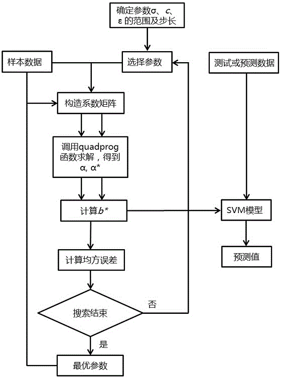
[0031] A method for predicting bottomhole flow pressure of a gas well in this embodiment, the prediction steps are as follows:

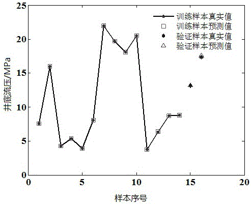
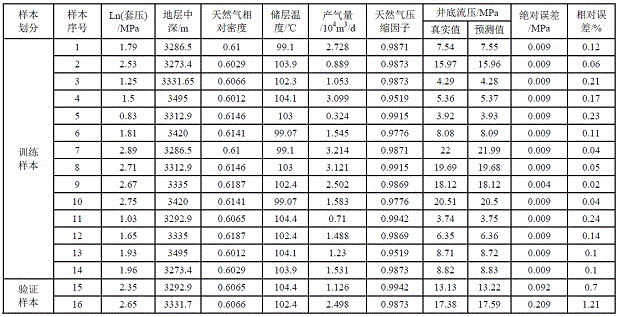
[0032] 1) Measure or collect the casing pressure, formation depth, relative density of natural gas, reservoir temperature, gas production, natural gas compression factor, and measured gas well bottomhole pressure parameters of a certain block. The specific methods include the following two aspects:

[0033] a Collect the existing production curves of the oilfield to obtain casing pressure and gas production parameters, see image 3 .

[0034] bCollect formation mid-depth parameters, reservoir temperature parameters, and measured well bottomhole flow pressure parameters, measure the relative density of natural gas with a balancer, and measure the compression factor of natural gas with a high-pressure physical property...


PUM


Abstract

The invention relates to a method for predicting gas well bottom flow pressure, which belongs to the fields of gas well dynamic analysis and working system optimization. Including (1) measuring or collecting the casing pressure, formation depth, relative density of natural gas, reservoir temperature, gas production, natural gas compression factor, and measured gas well bottomhole pressure parameters of a certain block; (2) making a gas drilling well Underflow pressure SVM predictor; (3) Input the measured or collected parameters into the SVM predictor for self-learning to determine the key parameters of the SVM predictor, namely the kernel function parameters , insensitivity coefficient and penalty factor (4) Input the casing pressure of the well to be predicted, the middle depth of the formation, the relative density of natural gas, the reservoir temperature, the gas production rate, and the compressibility factor of natural gas into the SVM predictor to obtain the prediction result of the bottomhole flowing pressure of the gas well to be predicted. The method is accurate and efficient, and it is a new practical method for predicting the bottom hole pressure of gas wells.

Description

technical field [0001] The invention relates to a method for predicting gas well bottom flow pressure, which belongs to the fields of gas well dynamic analysis and working system optimization. Background technique [0002] In the production process of gas wells, the bottom hole flow pressure is an important parameter for dynamic analysis. Obtaining the bottom hole flow pressure quickly and accurately, and then analyzing and optimizing the production system and working system, play a decisive role in the production of gas wells. The bottomhole flowing pressure of a gas well can be obtained by two methods: actual measurement with a downhole pressure gauge and calculation using a model. Usually, in the initial stage of gas field production, in order to obtain the dynamic parameters of the formation and deepen the understanding of the reservoir, a small number of gas wells will be installed with downhole pressure gauges to measure the bottom hole flow pressure. However, due to t...

Claims


Application Information

Patent Timeline
IPC IPC(8): E21B47/06E21B49/00
CPCE21B47/06E21B49/00
Inventor 狄勤丰陈薇华帅王文昌陈会娟
Owner SHANGHAI UNIV
Learn More