Tail heat utilization sieve hole flap dryer

A technology of sieve flaps and dryers, applied in progressive dryers, dryers, drying gas arrangement, etc., can solve problems such as difficulty in disassembly, achieve the effects of eliminating fatigue fractures, enhancing axial elasticity, and reliable use

Active Publication Date: 2018-11-16
武汉新实诚诺资源开发有限公司
View PDF6 Cites 0 Cited by
  • Summary
  • Abstract
  • Description
  • Claims
  • Application Information

AI Technical Summary

Problems solved by technology

In the actual assembly of shafts and holes with transmission threads, in order to achieve large load-bearing functions, the size of the threaded shafts and matching nut-like components are relatively large, and it is often easy and convenient to screw in during assembly, and It can realize the automatic and continuous locking of the bearing capacity during use, so it is very reliable, but when it is disassembled, the assembly is often very tight, and disassembly is very difficult. It is particularly important to realize simple and easy disassembly under this condition

Method used


Image

  • Tail heat utilization sieve hole flap dryer
  • Tail heat utilization sieve hole flap dryer
  • Tail heat utilization sieve hole flap dryer

Examples


Embodiment Construction

[0033] The present invention will now be further described in detail with reference to the accompanying drawings.

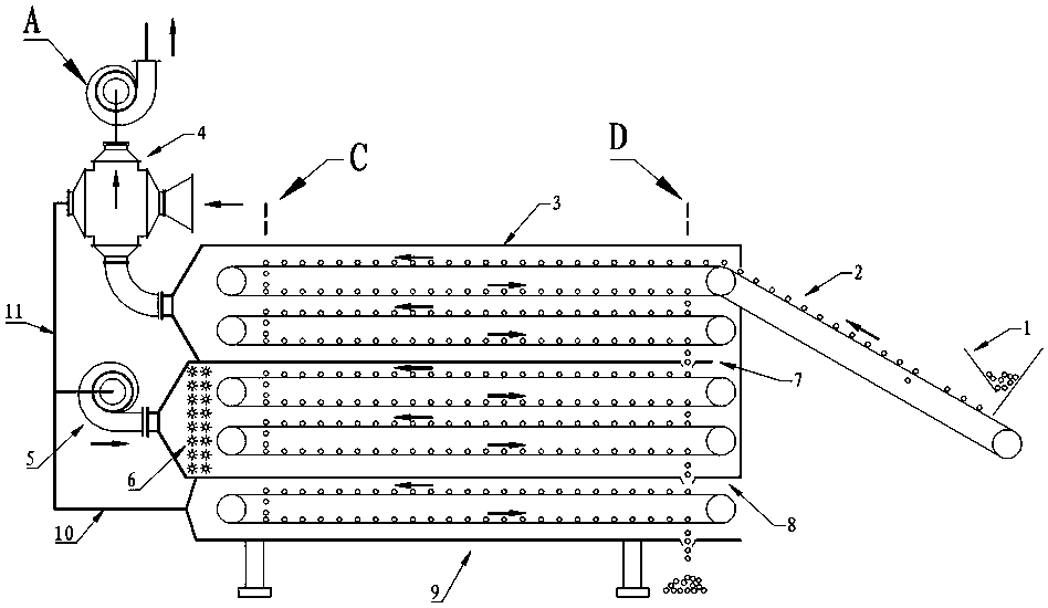
[0034] like figure 1 , figure 2 , image 3 , Figure 4 , Figure 5 , Image 6 , Figure 7 , Figure 8 and Figure 9 The shown tail heat utilizes a sieve-hole flap-type dryer, including a drying box body 3 and an induced draft fan A. The drying box body 3 is provided with a driving wheel, a passive wheel and a stainless steel sieve plate to form a top-down sieve-hole flap-type conveying 2; The drying cabinet 3 has a middle partition 7 and a lower partition 8 to divide the drying cabinet 3 into three drying areas: upper, middle and lower; The air inlet end of the heat exchanger 4 is connected to the atmosphere, the air outlet end is connected to the air inlet of the blower 5 through the air duct 11, and the air outlet of the blower 5 is connected to the steam fin heater 6 in the middle drying area; the lower drying area is connected back through the air du...


PUM


Abstract

The invention discloses a tail heat utilization sieve mesh turning-plate type drier. A drier box body is provided with a structure of sieve mesh turning-plate type conveying from top to bottom and is divided into an upper drying area, a middle drying area and a lower drying area by a middle baffle and a lower baffle. The upper drying area is connected with an induced draft fan through an air heat exchanger and then is drained; the air outlet end of the upper drying area is connected with an air inlet of an air blower through an air pipe; and an air outlet of the air blower is connected with a steam fin heater in the middle drying area. Blades of an impeller of the induced draft fan are arranged in a radiated mode with an impeller shaft being in radial symmetry and central symmetry, dust is cleaned up in time by centrifugal force, and safety accidents are avoided. The tail heat utilization sieve mesh turning-plate type drier improves the drying efficiency and achieves energy saving and emission reduction; more importantly, the disassembling technology of the induced draft fan is greatly improved, and the induced draft fan can simply eliminate the pressure of nut-like parts to the shaft shoulder end faces of screw rods when being disassembled, so that the problem that due to the threaded assembly mode, the induced draft fan is continuously and automatically locked under the load action and is not likely to be disassembled is effectively solved; and the tail heat utilization sieve mesh turning-plate type drier is particularly suitable for convenient disassembling of large draft fans after threaded locking, and the effect is very obvious.

Description

technical field [0001] The invention relates to a dryer, in particular to a tail heat-utilizing sieve flap type dryer which guides the fan without dust accumulation and is convenient for disassembly and maintenance. Background technique [0002] Due to its mature technology, strong adaptability, low operating cost and strong reliability, hot air dryer has become one of the preferred equipment for material drying. The screen-hole flap dryer is a kind of hot air dryer. It has the characteristics of simple structure and strong processing capacity. During the operation, the quality of the dried product is particularly uniform and reliable because the material is turned over layer by layer. The sieve flap dryer needs to continuously discharge hot and humid exhaust gas during the drying process to promote the drying process. Since the exhaust exhaust gas is rich in a large amount of tail heat, it is necessary to use the exhaust heat. Therefore, it is important to optimize the desi...

Claims


Application Information

Patent Timeline
Patent Type & Authority Patents(China)
IPC IPC(8): F26B15/06F26B21/00F04D17/16F04D29/28F04D29/30F04D29/26F04D29/054
CPCF04D17/16F04D29/054F04D29/263F04D29/281F04D29/30F26B15/06F26B21/002
Inventor 张旭银永忠张思言
Owner 武汉新实诚诺资源开发有限公司
Why Eureka
Try Eureka